


Installation
AVTrac • Installation
10
Step 3: Track, cont’d
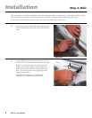
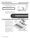
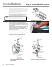
Pre-drill holes to secure connectivity box
End Plate
End Plate
Cover
Mounting Holes
The end of the
Connectivity Box
with three
mounting holes
faces back
towards the track.
3-3 Remove the cover panel and end plates
from the connectivity box.
Examine the bottom of the connectivity
box: one end has two mounting holes (one
in each corner), the other end has three
mounting holes (one in each corner and
one in the center). The end with three holes
faces back toward the track.
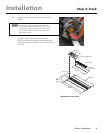
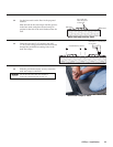
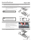
Align the end of the box with two
mounting holes with the end of the
base track. Mark where the mounting
holes in the bottom of the box lie over
the base track.
Using a 1/4" or 6 mm bit for drilling
metal (not supplied), drill at least three
mounting holes in the base track to
secure the connectivity box.
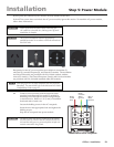
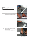
To fully assemble the track and attach
it securely to the floor (as shown in the
figure at right), follow the instructions
on the next page.
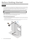
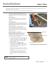
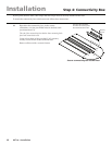
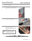
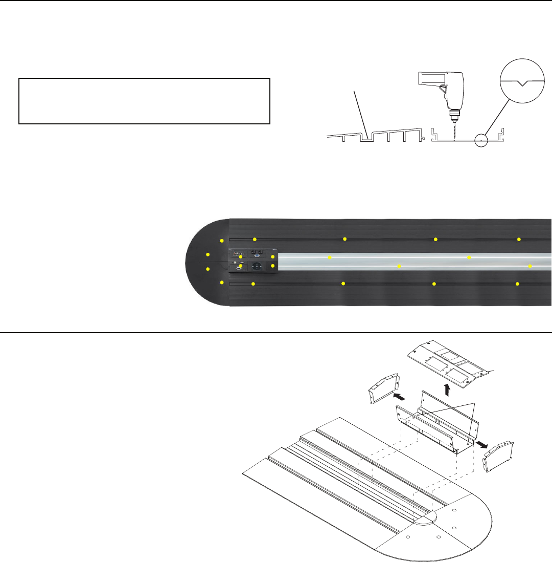
Pre-drill holes in track and ramps
3-2 Drill mounting holes in the shallow grooves of the
base track and side ramps using a 1/4" or 6 mm bit
for drilling metal (not supplied).
N
Mounting holes must be a maximum of 3'
(91 cm) apart and one must be within 6"
(15.2 cm) of each end of the track.
Shallow Groove
in Side Ramp
(pre-drill holes)
Shallow Groove
in Base Track
(pre-drill holes)
Side Ramp
Base Track
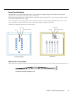
To ensure that all components are securely
attached to the floor, Extron recommends that
the predrilled holes should closely follow the
pattern shown in this figure.
Positions of mounting holes