


RS-232 Programming • Appendix A
Extron • System 5
cr
Switcher • User’s Manual
Female
Connector
Male
Connector
5
1
6
9
9
6
5
1
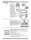
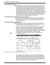
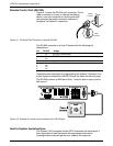
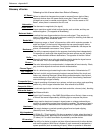
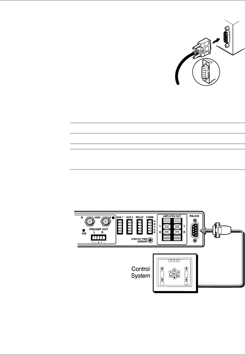
Remote Control Port (RS-232)
Figure A-1 shows the RS-232 port connector. This is
used to connect to a host, or external controlling
device, such as a computer or control panel that
can generate the proper command codes and
recognize the System 5 responses.
.
Figure A-1. The Serial Port Connector is wired for RS-232
The RS-232 connector is a 9-pin D female with the following pin
designations:
Pin RS-232 Usage
1 n/u
2 Tx RS-232 Transmit Data
3 Rx RS-232 Receive Data
4 n/u
5 Gnd Signal Ground (both)
6 n/u
7 n/u
8 n/u
9 n/u
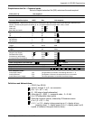
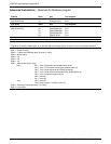
Commands and responses for programming the System 5 Switcher from
a Host system connected to the RS-232 port are listed on the next page.
The RS-232 protocol is 9600 baud, 8-bit, 1 stop bit with no parity and no
flow control.
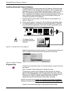
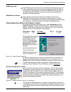
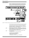
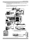
Figure A-2. Example of a touch panel connected to the RS-232 port.
Host-to-System 5
crcr
crcr
cr Instructions
The System 5 will recognize certain ASCII characters as instructions. It
then responds to those characters with appropriate information.
Unrecognizable codes will get an error code as the response.
A-1