


Reference • Appendix B
Extron • System 5
cr
Switcher • User’s Manual
System 5
crcr
crcr
cr Options
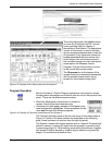
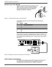
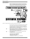
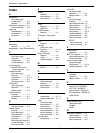
Figure B-1 illustrates the options and accessories that operate with the
System 5. The standard accessories installation is covered in Chapter 2
and each option has its own User’s Guide. This section summarizes the
three options: SCP 100, IR Broadcaster and Display Power Sensor.
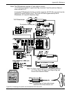
Figure B-1. The options connectors are located to the right side of the rear panel.
All of the necessary connectors are provided with the products, but cables
must be custom made according to the requirements of the installation.
The Display Power Sensor is also shown in Figure B-1. Its cable is one-
to-one, ring = signal, tip = +12 volts and sleeve = ground. The optional IR
Broadcaster uses the same contact assignments.
________ When connecting a Power Sensor or IR Broadcaster, remember that the
System 5 supplies the +12 volts to the tip of the connector. Therefore the
cable should be plugged into the option device before connecting it to the
System 5 rear panel, where the voltage source is.
________ Do not plug any other devices into the rear panel connectors, except
those described here.
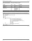
For detailed instructions, see appropriate document.
• SCP 100 Control Pad, P/N 68-390-01
• Display Power Sensor, P/N 68-391-01
• IR Broadcaster, P/N 68-392-01
• IR Broadcaster with Emitter connector, P/N 68-392-02
B-1