


Appendix B • Reference
Extron • System 5
cr
Switcher • User’s Manual
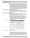
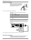
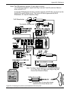
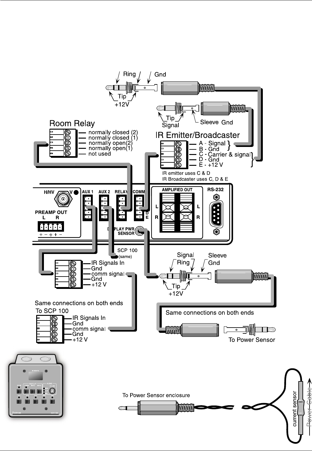
To IR Broadcaster
To projector remote jack
Notes: The IR Broadcaster requires a 3-wire cable to connect:
+12 V from tip to contact E, signal from Ring to contact C and Ground from Sleeve to
either contact B or D.
If using the IR Broadcaster that has an emitter connector (60-272-02), use pin A from the
System 5 for signal without carrier. The carrier will then be generated by the IR
Broadcaster, for a specific frequency range.
Note: The Power Sensor requires a 3-wire cable to connect:
+12 V from Tip to Tip, signal from Ring to Ring and
Ground from Sleeve to Sleeve.
Note: The sensor has a 2-wire cable already
attached to the Power Sensor unit.
B-2
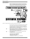
Figure B-2. Connecting the options and accessories to the rear panel.