


Chapter 1 • Introduction and Features
Extron • System 5
cr
Switcher • User’s Manual
Infrared Learning for System Control
The IR receiver window on the front panel also serves as a learning port
to add IR signals from other sources to the System 5 panel functions.
Then, when a panel function is selected, the learned IR signal is
transmitted into the room through the hard-wired IR emitter, or the
optional IR Broadcaster, to be received by the projector. IR commands for
the projector can be associated with each of the Display buttons (Power,
Mute and Mode) on the front panel as well as with each of the five input
buttons. Thus the System 5 switcher can control the projector. Stored
commands (learned or uploaded) in the System 5 memory are also
effective when using the IR 40, SCP 100 or RS-232 controls.
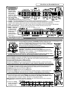
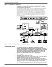
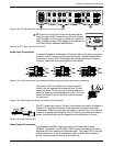
As an example, IR commands for the projector shown in Figure 1-1 can
be stored in the System 5 memory such that when the VID1 input is
selected, the projector will switch to its composite video mode. Selecting
VID2 input could send a command to tell the projector to switch to S-video
mode.
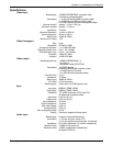
Standard Features
• 250 MHz bandwidth (-3 dB)
• Audio preamp with 2-channel stereo outputs
• Audio breakaway (switch audio and video separately, with RS-232)
• Audio input levels may be preset individually and then adjusted by the
master volume control.
• Five Inputs - computer video, RGBS, RGBHV, composite video or S-video
• Internal audio amplifier - 12 watt/channel, with adjustable output
• Room control - relay control of lights, window shades, display screen, etc.
• Projector control - display power, mute, mode (learned IR commands)
• Learns IR remote commands - from a library or through the front panel
• Memory stores IR commands that are learned, or uploaded through a PC.
(Procedure in Chapter 4.)
• RS-232 programming, with Simple Instruction Set (SIS)
• Triple-action switching (blank screen while switching between inputs)
• Special mounting brackets allow the System 5 to be mounted on a wall or
under a table, plus standard brackets are included for rack-mounting.
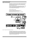
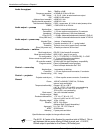
Inputs
_______ The four rear panel inputs described here include a 5-pole, captive screw
connector for 2-channel stereo audio, balanced or unbalanced signals.
• Computer video input is provided on the front panel through a VGA
(female HD 15 pin) connector (PC1). This allows for quick connection of a
laptop computer without having to access the rear panel of the switcher.
• Computer video may also be connected through BNC connectors to the
PC2 and PC3 inputs, through an interface, such as an RGB 406, as
shown in Figure 1-1.
• The VID1 and VID2 inputs can be either composite or S-video signals,
both through BNC connectors.
Outputs
• The System 5 provides video outputs for RGBS, RGBHV, Composite and
S-video formats. One output is active at any one time.
• Audio preamp output for either balanced or unbalanced audio signals is
available through a 5-pole, captive screw connector.
• An internal, 12 watt/channel audio amplifier drives non-powered speakers.
• Stored IR commands output through emitter or broadcaster.
1-2