


DTP T EU 332, DTP T EU 232, DTP T MK 332, and DTP T MK 232 • Installation and Operation 4
Installation and
Operation
This section contains information for mounting, connecting, wiring, and operating the
DTP T EU 332, DTP T MK 332, DTP T EU 232, and DTP T MK 232 . Topics in this section
include:
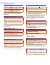
• Installation Overview
• Installing the Junction Box or European Cable Channel System
• Rear Panel and Side Panel Features
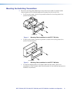
• Mounting the Switching Transmitters
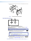
• Front Panel Connectors
• Connection and Wiring Details
• Operation
• Troubleshooting — If no Image Appears
Installation Overview
All models can mount into junction boxes. The DTP T EU 332 and DTP T EU 232 can mount
into a European cable channel system (also known as a “trunking system”).
For junction boxes, the DTP T EU 332 and DTP T EU 232 mount into European junction
boxes and the DTP T MK 332 and DTP T MK 232 mount into MK junction boxes.
To mount and connect the transmitters, consider the following:
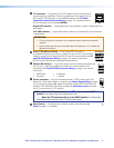
Ensure there is enough space between the rear panel and the back of the junction box
or European cable channel system to fit connectors. The switchers require a minimum
depth of 36 mm (1.4 inch).
NOTE: The depth of the junction box or European cable channel system may vary.
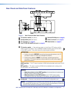
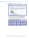
If you are using a European cable channel system with a DTP T EU 332 or DTP T EU 232,
ensure the transmitter fits in the desired channel. Figure 2, on the next page, shows the
dimensions of both EU transmitter models. The depth of all four transmitters is the same.
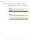
If necessary, prepare the mounting surface.
CAUTION: Failure to check the items listed below may result in personal injury or
property damage.
ATTENTION : La non-vérification des éléments listés ci-dessous peut provoquer
des blessures ou dommages matériels.
Ensure there are no utility cables or pipes at the intended location that might be
damaged or cause injury when installing the device.
Check that the installation meets the building, electrical, and safety codes.