


DTP T EU 332, DTP T EU 232, DTP T MK 332, and DTP T MK 232 • Installation and Operation 15
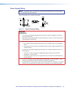
Power Supply Wiring
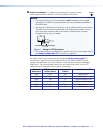
NOTE: The power supply included with the switching transmitter can normally power
the transmitter and the receiver.
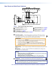
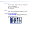
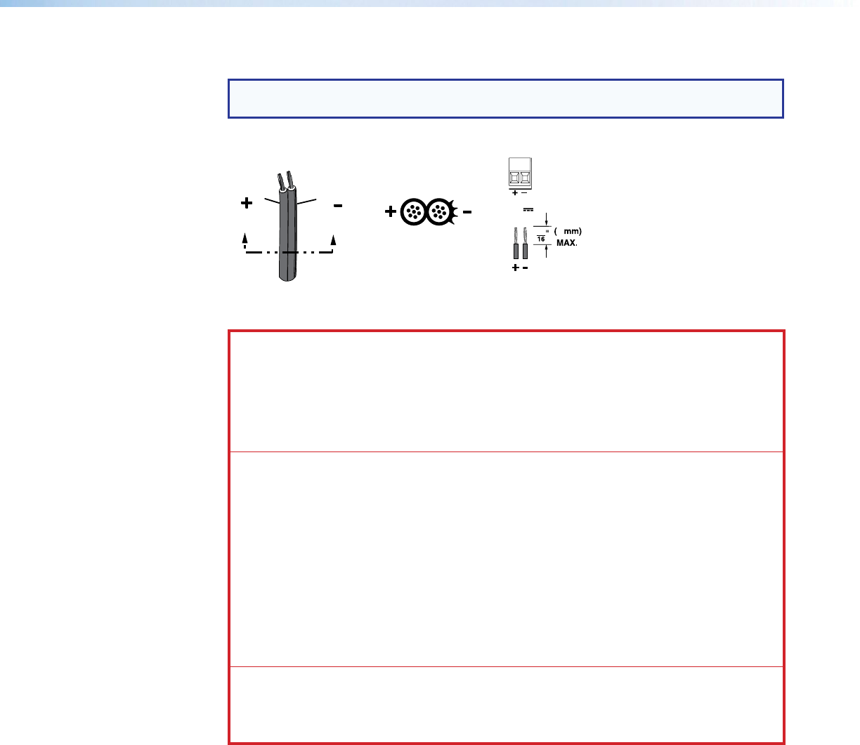
Figure 13 shows how to wire the connector.
Power Supply
Output Cord
Direct Insertion
Connector
SECTION A–A
Ridges
Smooth
AA
3
5
1.0 A MAX
POWER
12V
Figure 13. Power Connector Wiring
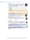
CAUTION:
ATTENTION :
• The wires must be kept separate while the power supply is plugged in. Remove
power before wiring.
• Les deux cordons d’alimentation doivent être tenus à l’écart l’un de l’autre quand
l’alimentation est branchée.
• The length of exposed wires is important. The ideal length is 3/16 inch (5 mm).
• Any longer and the exposed wires may touch, causing a short circuit between
them.
• Any shorter and the wires can be easily pulled out even if tightly fastened by the
captive screws.
• La longueur des câbles exposés est importante. La longueur idéale est de 5mm
(3/16inches).
• S’ils sont un peu plus longs, les câbles exposés pourraient se toucher et
provoquer un court circuit.
• S’ils sont un peu plus courts, ils pourraient sortir, même s’ils sont attachés par
les vis captives.
• Do not tin the power supply leads before installing them in the connector. Tinned
wires are not as secure in the connector and could be pulled out.
• Ne pas étamer les conducteurs avant de les insérer dans le connecteur. Les câbles
étamés ne sont pas aussi bien fixés dans le connecteur et pourraient être retirés.