


DTP T EU 332, DTP T EU 232, DTP T MK 332, and DTP T MK 232 • Remote Control 21
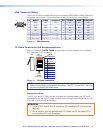
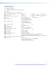
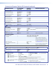
Symbol definitions
]
= Carriage return/line feed
}
= Carriage return (no line feed)
| = Pipe (can be used interchangeably with the
}
character)
• = space
E
= Escape key
W = Can be used interchangeably with the
E
character
X! = Input number (for switching) 0
= No input
1
= HDMI input
2
=
VGA
input
X@ = Switch mode 0 = Manual 1 = Auto switch VGA (default) 2 = Auto switch HDMI
X# = Input number (for audio configuration) 0
= Always output
1
= HDMI input
2
= VGA input
X$ = Status 0 = Off, disabled, not detected 1 = on, enable, or detected
X% = Input HDCP status 0 = No source is detected
1 = Source is detected with HDCP
2 = Source detected without HDCP
X^ = Output HDCP status 0 = No sink is detected
1 = Sink is detected with HDCP
2 = Sink is detected without HDCP
X& = Color bit depth mode 0 = Auto 1 = 8-bit
X* = EDID See the table on page 23.
X( = User EDID location 66 or 67
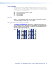
X1) = Raw EDID data 128 or 256 bytes of hexadecimal data
X1! = Resolution and rate in plain text Example: 1920x1200•@60Hz
X1@ = Switch position 0 = DTP 1 = HDBT
X1# = Pixel phase 00 – 63 (32 = default)
X1$ = Total pixels Depends on input rate
X1% = Horizontal and vertical start 000 – 255 (128 = default)
X1^ = Switcher name A text string of up to 24 alphanumeric characters and minus sign/hyphen (-).
No blank or space characters are permitted as part of a name.
The first letter must be a letter, and the last character must not be a minus sign/hyphen.
X1& = Firmware version number to second decimal place (x.xx)
X1* = Verbose mode 0 = clear/none
1 = verbose mode (default for RS-232 or USB) (default)
2 = tagged responses for queries
3 = verbose mode and tagged for queries