


Operation, cont’d
IN1508 Scaling Presentation Switcher • Operation3-38
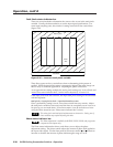
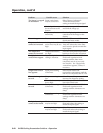
Total Pixels status indicator bar
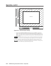
There are several methods to determine the correct value to use in the total pixels
variable. Usually, the best method is to use the input signal specifications. For
some input sampling rates, the switcher’s setting can result in fine vertical lines
(figure 3-26).
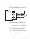
Total Pixels
Active
Area
Blanking Area
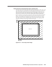
Figure 3-26 — Incorrect total pixels variable
These lines appear as fuzzy vertical bars when an alternating pixels pattern is
applied. When the total pixels setting is improperly adjusted the entire image can
have a noisy or darkened appearance. Adjusting the phase corrects this.
As an approximate setting, multiply the active pixels setting (see “Active Pixels and
Active Lines status indicator bars”, earlier in this chapter) by a factor of 1.3.
If the input pixel clock rate is known, the input total pixels setting can be calculated
with this equation:
total pixels = input pixels clock ÷ input horizontal scan rate
Once a preliminary setting is saved, some faint vertical lines may remain. Adjust
the total pixels variable as necessary until the lines are completely out of view or as
far apart as you can make them. If one line remains, it can be moved out of view
using the Phase status bar (see “Phase status indicator bar”, below).
The active pixels and total pixels adjustments are interactive. Setting one of
these variables may require adjusting the other.
Phase status indicator bar
The Phase adjustment is available for RGBHV, RGBS, RGsB, and progressive
component video inputs only.
The Phase status indicator bar shows, and allows you to adjust, the phase
adjustment setting. The phase control adjusts the amount of phase shift applied to
the input video signal. Use the front panel or IR remote control
and buttons to
increase or decrease the amount of phase shift through a range of 0 to 31.