


IN1508 Scaling Presentation Switcher • Serial Communications4-2
Serial Communications
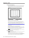
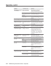
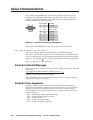
The switcher’s rear panel Remote 9-pin D female connector (figure 4-1) can be
connected to the RS-232 serial port output of a host device such as a computer
running the HyperTerminal utility or a control system. This connection makes
software control of the switcher possible.
RS-232 FunctionPin
1
2
3
4
5
6
7
8
9
—
TX
RX
—
Gnd
—
—
—
—
Not used
Transmit data
Receive data
Not used
Signal groun
d
Not used
Not used
Not used
Not used
51
96
Female
Figure 4-1 — Remote connector pin arrangement
The protocol is 9600 baud, 8-bit, 1 stop bit, no parity, and no flow control.
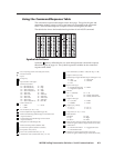
Host-to-Switcher Instructions
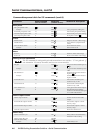
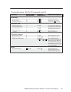
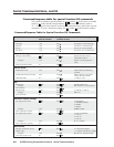
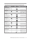
The switcher accepts (Simple Instruction Set) SIS
™
commands through the
RS-232 port. SIS commands consist of one or more characters per command field.
They do not require any special characters to begin or end the command character
sequence. Each switcher response to an SIS command ends with a carriage return
and a line feed (CR/LF = ), which signals the end of the response character
string. A string is one or more characters.
Switcher-Initiated Messages
When a power-up occurs, the switcher responds by sending the following message
to the host:
Copyright 2005, Extron Electronics, IN1508, Version x.xx
Version x.xx is the firmware version number.
The switcher does not expect a response from the host; but, for example, the host
program might request a new status.
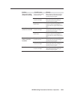
Switcher Error Responses
When the switcher receives an SIS command and determines that it is valid, it
performs the command and sends a response to the host device. If the switcher is
unable to perform the command because the command is invalid or contains
invalid parameters, the switcher returns an error response to the host. The error
response codes are:
E01 — Invalid input channel number (too large)
E09 — Invalid function number (too large)
E10 — Invalid command
E13 — Invalid value (out of range)
E17 — Invalid command for signal type