


Rear Panels
1 2 3 4
50/60 Hz
100-120V 10A
ALARM
100-120V TOTAL LOAD 10A MAX
LAN
S/N XXXXXXXXX E0000
0408
00-05-A6-XX-XX-XX
1
2
3
4
5
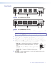
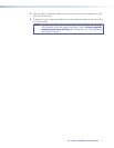
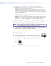
Figure 4. IPL T PCS4 Rear Panel (120 VAC)
50/60 Hz
200-240V 10A
ALARM
200-240V TOTAL LOAD 10A MAX
LAN
S/N XXXXXXXXX E0000 0408
00-05-A6-XX-XX-XX
123
4
1
2
3
4
5
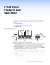
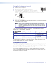
Figure 5. IPL T PCS4i Rear Panel (220 VAC)
a Power connector — Connect a power cord from the AC power supply to this male IEC
power input receptacle.
NOTE: For the IPL T PCS4, use the supplied 14 AWG IEC power cord (part
number 27‑407‑01).
b Output receptacles — Connect power cords from up to four devices to these
three-prong female U. S. (IPL T PCS4) or IEC (IPL T PCS4i) power output receptacles.
c Alarm relay — Connect a relay-controllable detection device to this single-pole,
single-throw relay connector. (The default condition for this relay is normally open.)
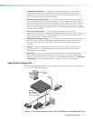
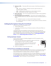
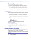
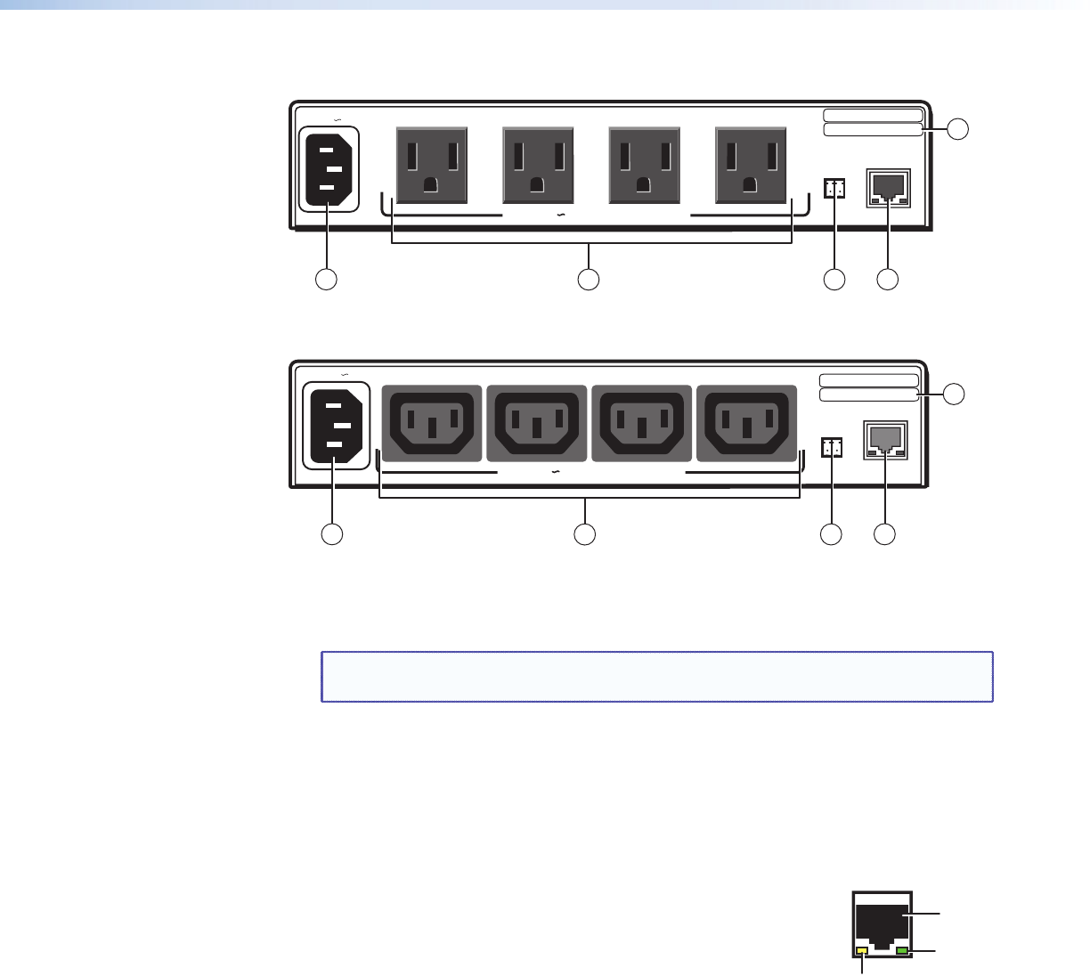
d LAN connector and LEDs — An Ethernet connection can be used on an ongoing basis
to monitor and control the PCS4 (and the devices connected to it).
• RJ‑45 port — Plug a patch cable into this RJ-45 female socket,
LAN
RJ-45
Port
Link
LED
Activity
LED
and connect the other end to a network switch, hub, router,
or PC.
• Link LED — This green LED lights to indicate a good network
connection.
• Activity LED — This yellow LED blinks to indicate network
activity.
e UID # label — Contains the unique User ID number (MAC address) of the unit (for
example, 00-05-A6-00-00-01).
IPL T PCS4 • Installation and Rear Panel 5