


MMX 32 VGA A • Installation and OperationMMX 32 VGA A • Installation and Operation
Installation and Operation, cont’d
2-6 2-7
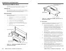
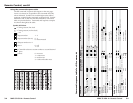
Outputs
2
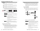
Video output 1 — Connect an output monitor or other VGA
device to this female 15-pin HD connector.
3
Audio output 1 — Connect speakers to this 3.5 mm stereo jack.
4
Video output 2 — Connect a projector or other RGBHV video
output device to these five BNC connectors.
5
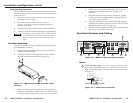
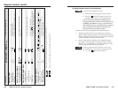
Audio output 2 — Connect speakers to this 5-pole 3.5 mm
captive screw connector. Wire the captive screw connector for
stereo output as shown in figure 2-6. Use the supplied tie-wrap
to strap the audio cable to the extended tail of the connector.
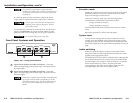
Ring
Sleeve(s)
Tip
Tip
Ring
Sleeve(s)
Tip
Tip
Unbalanced Stereo Output Balanced Stereo Output
NO GROUND HERE.
NO GROUND HERE.
LR
Do not tin the wires!
Figure 2-6 — Audio output connections
CAUTION
Connect the sleeve to ground (Gnd). Connecting
the sleeve to a negative (-) terminal will damage the
audio output circuits.
The length of exposed (stripped) copper wires is critical.
The ideal length is 3/16” (5 mm).
• If the stripped section of wire is longer than 3/16”, the
exposed wires may touch, causing a short circuit
between them.
• If the stripped section of wire is shorter than 3/16”,
wires can be easily pulled out even if tightly fastened
by the captive screws.
Do not tin the stripped power supply leads before
installing the captive screw connector. Tinned wires are
not as secure in the captive screw connectors and could
be pulled out.
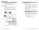
Remote control connections
6
Remote connector — Connect a computer or RS-232 control
module to this female 9-pin D connector to allow remote control
using the Extron Simple Instruction Set
™
(SIS
™
) or the Extron
Universal Switcher Control Program. Alternatively, connect a
contact closure device such as an Extron remote control
Architectural Adapter Plate (AAP or MAAP). See chapter 3,
“Remote Control”, for more information.
7
Tally Power connector — This 2-pole captive screw connector
provides power to light the LEDs on Extron MMX 32 AAP
(part #70-277-01, -11, or -21) or MMX 32 MAAP (part #70-277-12,
or -22) contact closure remote control panels. Connect the 5V
and Gnd (-) 2-pole captive screw connector on the AAP or
MAAP to this connector. See chapter 3, “Remote Control”, for
more information.
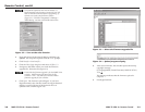
Power connection
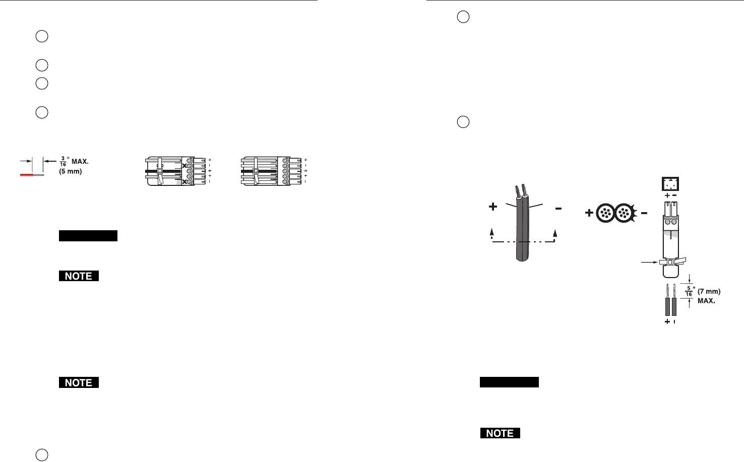
8
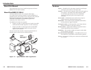
Power connector — An external 12V power supply is included
with the unit. Plug it into this 2-pole 3.5 mm captive screw
connector. Wire the connector as shown in figure 2-7. Use the
supplied tie-wrap to strap the power cable to the extended tail
of the connector.
Power Supply
Output Cord
SECTION A–A
Ridges
S
mooth
AA
Captive Screw
Connector
Tie Wrap
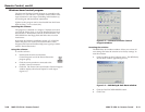
Figure 2-7 — Power connection wiring
CAUTION
Power supply voltage polarity is critical. Incorrect
voltage polarity can damage the power supply and
the MMX. Identify the power cord negative lead by
the ridges on the side of the cord (figure 2-7).
The length of exposed (stripped) copper wires is critical.
The ideal length is 5/16" (7 mm).
• If the stripped section of wire is longer than 5/16”, the
exposed wires may touch, causing a short circuit
between them.
• If the stripped section of wire is shorter than 5/16”,
wires can be easily pulled out even if tightly fastened
by the captive screws.