


Remote Control, cont’d
MMX 32 VGA A • Remote Control MMX 32 VGA A • Remote Control3-12
Updating the firmware
Firmware updates periodically become available on the Extron
Web site. To load a firmware update:
1. Download the update file from the Extron Web site
(www.extron.com).
2. Run the Universal Switcher Control Program.
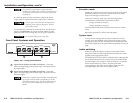
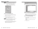
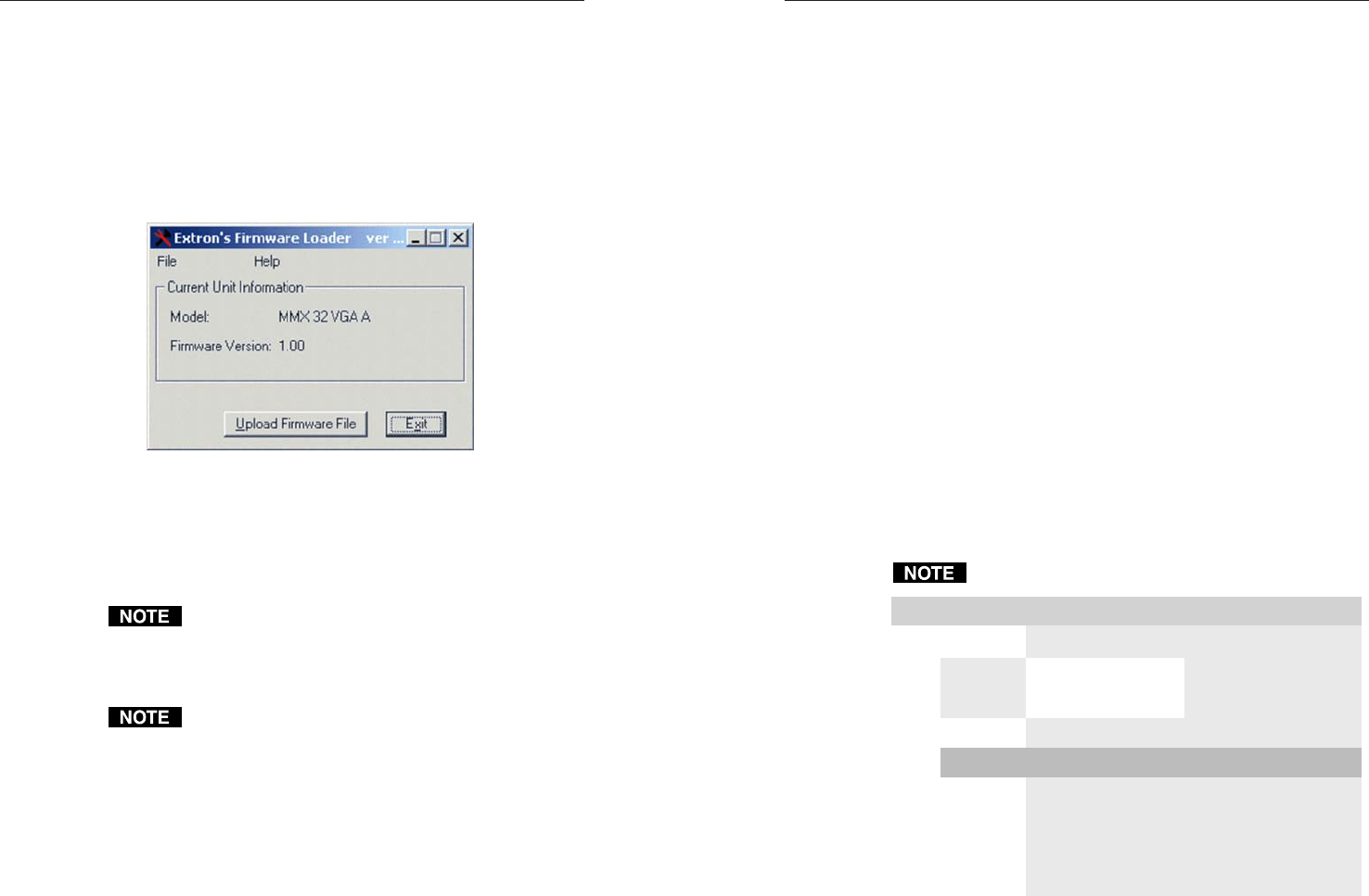
3. On the File menu, click Update Firmware. The Firmware
Loader window appears (figure 3-7).
Figure 3-7 — Firmware Loader window
4. Click the Upload Firmware File button.
5. Locate the update file you downloaded from the Web site
and click Open. The Universal Switcher Control Program
loads the update.
The firmware update file must have an .s19 extension. If
it does not have that extension it will not work properly.
6. When the program is finished loading the update, click
Exit. The Universal Switcher Control Program closes.
If the firmware loader utility exits before the status bar
has progressed completely across the indicator window,
the firmware may be corrupted and may no longer
respond to the Universal Switcher Control Program or
the Firmware Loader utility. In this condition, the
firmware upload can be accomplished only by using SIS
commands. See Loading firmware using an SIS
command on page 3-7.
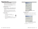
Using the help system
For information about program features, you can access the help
program in any of the following ways:
• From the Extron Electronics program group, double-click
the Signal Enhancement Products Help icon.
• From within the Universal Switcher Control Program,
click Help on the task bar.
• From within the Universal Switcher Control Program,
press the F1 key.
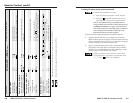
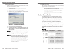
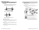
Contact Closure Control
The MMX 32 VGA A can be controlled remotely using the
optional Extron MMX 32 AAP contact closure control panel
(part #70-277-01, -11, or -21) or the MMX 32 MAAP contact
closure panel (part #70-277-12 or -22). Each panel controls one
output and has three input selector buttons and LEDs.
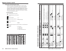
The contact closure system uses the pins on the Remote
connector that are not assigned to RS-232 control (see the table
below for pin assignments). Each contact closure pin
corresponds to an input/output connection, or tie. A tie is made
when one pin is connected to ground. Each pin returns a tally
out signal to the remote control panel after a tie is made,
lighting the control panel LED corresponding to the selected
input.
For contact closure do not use pins 2 or 3.
niP 232-SR erusolctcatnoC noitcnuF
1—
n#1I
1 to output 1tupni
2
XT— )-(atadtimsnarT
3
XR— )+(atadevieceR
4—
2/Out#1#nI
5 dnG dnG dnuorglangiS
6—
3/Out#1#nI
7— 1/Out#2#nI
8— 2/Out#2#nI
9 — 3/Out#2#nI
/Out#1
Tie
2 to output 1tupniTie
3 to output 1tupniTie
1 to output 2tupniTie
2 to output 2tupniTie
3 to output 2tupniTie
3-13