


MMX 32 VGA A • Installation and OperationMMX 32 VGA A • Installation and Operation
Installation and Operation, cont’d
2-52-4
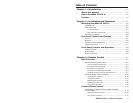
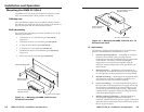
Rack mounting instructions
On the standard rack shelf, the switcher mounts in one of four
locations to the rear of the rack or in one of four locations to the
front of the rack.
1. Remove rubber feet if they were previously installed on
the bottom of the switcher.
2. Mount the switcher on the rack shelf, using two
4-40 x 3/16" screws in opposite (diagonal) corners to
secure it to the shelf.
3. Install blank panel(s) or other unit(s) on the rack shelf.
4. Attach the rack shelf to the rack using the supplied bolts.
Only products in the VersaTools line can be mounted on
a VersaTools shelf. Most 1U rack-mountable Extron
products can be mounted on the standard and basic
shelves.
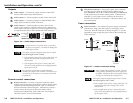
Furniture mounting
Furniture mount the switcher using the optional mounting kit
(part #70-212-01) as follows:
1. Remove rubber feet if they were previously installed on
the bottom of the switcher.
2. Attach the furniture mounting brackets to the switcher
with the provided machine screws (figure 2-3).
MMX 32 VGA A
OUTPUT 1
2
1 3
OUTPUT 2
2
1
3
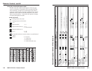
Figure 2-3 — Mounting the MMX 32 VGA A under
furniture
3. Hold the switcher with the attached brackets against the
underside of the table or other furniture. On the mounting
surface, mark the location of the screw holes of the bracket.
4. Drill 3/32" (2 mm) diameter pilot holes, 1/4" (6.3 mm)
deep in the mounting surface at the marked screw
locations.
5. Insert #8 wood screws into the four pilot holes. Tighten
each screw into the mounting surface until just less than
1/4" of the screw protrudes.
6. Align the mounting screws with the slots in the brackets
and place the switcher against the surface, with the screws
through the bracket slots. See figure 2-3.
7. Slide the switcher slightly forward or back, then tighten all
four screws to secure the unit in place.
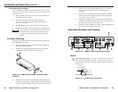
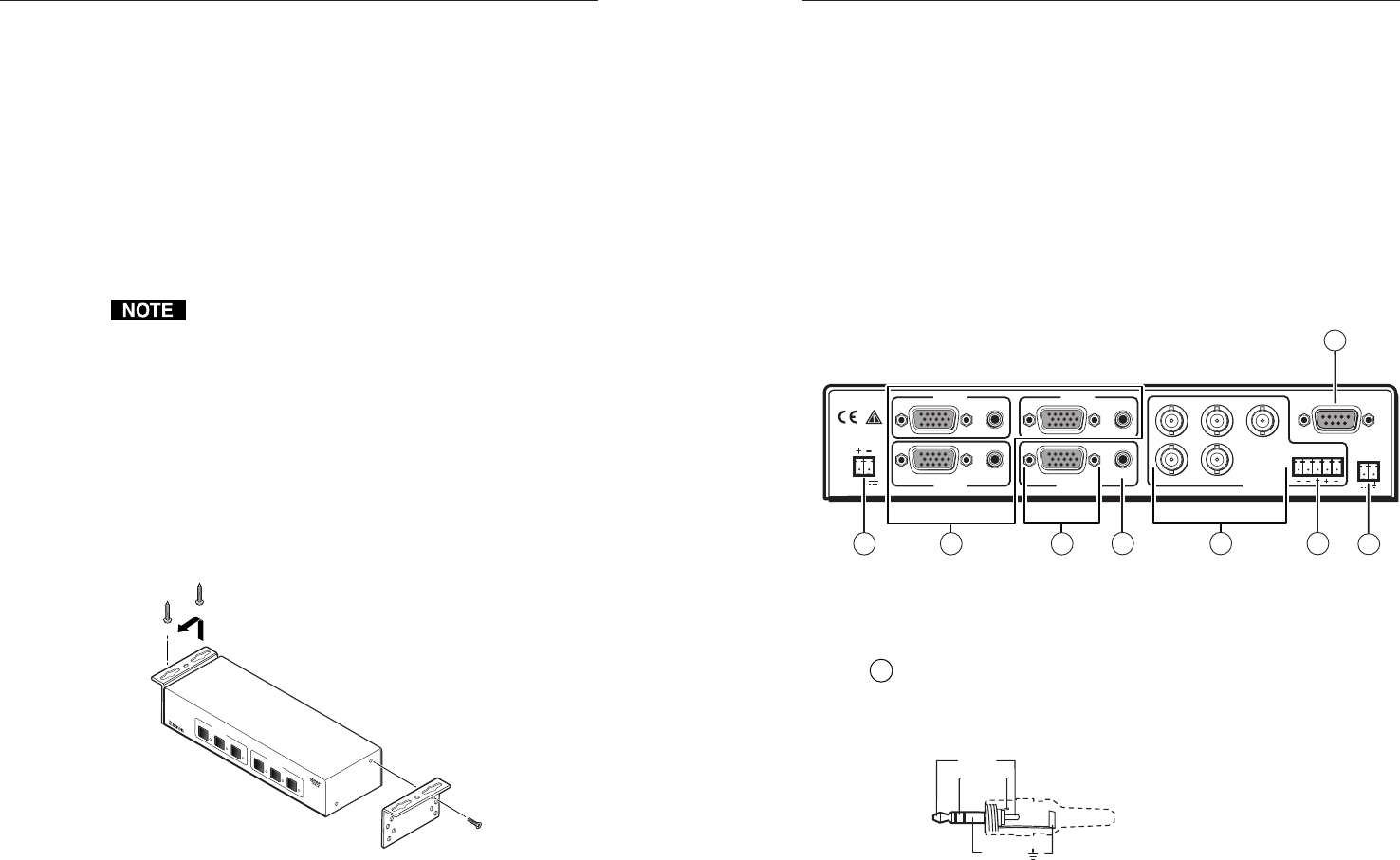
Rear Panel Features and Cabling
LR
POWER
12V
.5A MAX
INPUT 2
INPUT 1
AUDIO
AUDIO
OUTPUT 1 OUTPUT 2
INPUT 3
R
H
GB
V
AUDIO
REMOTE
AUDIO
TALLY
PWR
5V
2
3
8
5
7
6
4
1
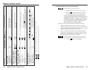
Figure 2-4 — MMX 32 VGA A rear panel features
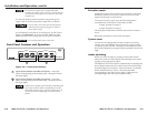
Inputs
1
Video and audio inputs — Connect computer video sources to
these female 15-pin HD connectors. Connect audio sources to
these 3.5 mm stereo jacks. Wire the audio connectors as shown
in figure 2-5.
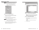
Sleeve ( )
Ring (
R
)
Tip (L)
3.5 mm Stereo Plug Connector
(balanced)
Figure 2-5 — Audio input connection