


Remote Control
MMX 32 VGA A • Remote Control MMX 32 VGA A • Remote Control
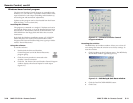
Simple Instruction Set control
Host-to-switcher instructions
The switcher accepts SIS commands through the remote
connector. SIS commands consist of one or more characters per
command field. They do not require any special characters to
begin or end the command character sequence. Each switcher
response to an SIS command ends with a carriage return and a
line feed (CR/LF =
), which signals the end of the response
character string. A string is one or more characters.
Switcher-initiated message
The following copyright message is initiated by the switcher
when it is first powered on. Vx.xx is the firmware version
number.
(C) Copyright 2003, Extron Electronics, MMX 32 VGA A, Vx.xx
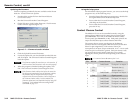
Switcher error responses
When the switcher receives an SIS command and determines
that it is valid, it performs the command and sends a response
to the host device. If the switcher is unable to perform the
command because the command is invalid or contains invalid
parameters, the switcher returns an error response to the host.
The error response codes are:
E01 — Invalid input channel number (too large)
E10 — Invalid command
E12 — Invalid output number (too large)
E13 — Invalid value (out of range)
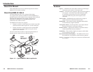
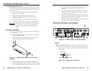
The switcher’s rear panel Remote connector can be connected to
the serial port output of a host device such as a computer or
control system, or to a contact closure device such as the Extron
MMX 32 AAP panel (part #70-277-01, -11, or -21) or
MMX 32 MAAP panel (part #70-277-12 or -22).
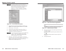
RS-232 Control
The RS-232 Remote connection makes software control of the
switcher possible via the Extron Simple Instruction Set (SIS) or
the Extron Windows
®
-based control program.
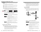
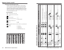
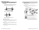
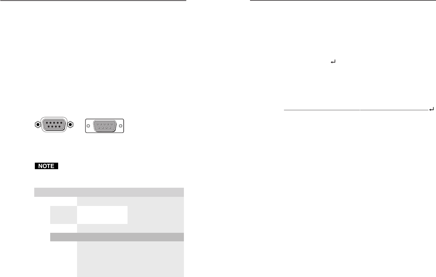
The Remote connector on the MMX 32 VGA A is a female
9-pin D connector (figure 3-1). Pins not used for RS-232 control
are assigned to contact closure control as described later in this
chapter. The Remote connector pin assignments are listed in the
table below.
51
9
5
9
6
Female Male
1
6
Figure 3-1 — Remote connector pin arrangement
For RS-232 use only pins 2, 3, and 5.
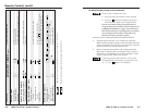
Remote connector pin assignment table
niP 232-SR erusolctcatnoC noitcnuF
1—
n#1I
1 to output 1tupni
2
XT— )-(atadtimsnarT
3
XR— )+(atadevieceR
4—
2/Out#1#nI
5 dnG dnG dnuorglangiS
6—
3/Out#1#nI
7— 1/Out#2#nI
8— 2/Out#2#nI
9— 3/Out#2#nI
/Out#1
Tie
2 to output 1tupniTie
3 to output 1tupniTie
1 to output 2tupniTie
2 to output 2tupniTie
3 to output 2tupniTie
The RS-232 protocol for this connector is 9600 baud, 8-bit, 1 stop
bit, no parity.
3-3
3-2