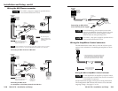
MLA-VC10 • Installation and Setup
Installation and Setup, cont’d
MLA-VC10
A
Appendix A
Specifications, Part Numbers,
and Accessories
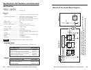
Specifications
Included Parts
Cables
MLA-VC10 Functional Block Diagram
2-16
• The amplifier accepts a higher control voltage than the
MLA-VC10 provides, so the amplifier will not reach its
highest volume level. Try another amplifier with a lower
control voltage requirement.
If audio output does not reach the amplifier’s maximum
volume
• If you use an MLA-VC10 with an amplifier/mixer that has a
control voltage requirement above 10VDC, the maximum
volume may not be reached.
If volume changes lead to erratic variation in output
volumes
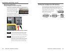
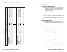
• Verify that each DIP switch is set either all the way up or all
the way down, not partway between up and down
positions.
3
4
1
2
7
8
5
6
3
4
1
2
7
8
5
6
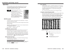
ON
CONFIGURATION
0 to 10.0VDC 0 to 4.98VDC NOT HALFWAY
UP
DOWN
CONFIGURATION
Leaving a DIP switch in the middle can cause
unpredictable changes in volume: the switch
intermittently varies between on and off settings, yielding
control voltages from two different ranges: one range
that’s appropriate for your equipment, and one that isn’t.
If the audio output can still be heard when the MLA-VC10
has a volume setting of 0VDC
• Check the gain and level settings on the amplifier or mixer.
Adjust the gain so that you don’t hear any audio output
when the MLA-VC10 is set for 0VDC output (minimum
volume).


