


Installation and Setup
2-7
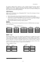
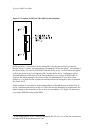
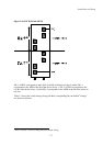
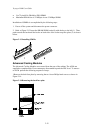
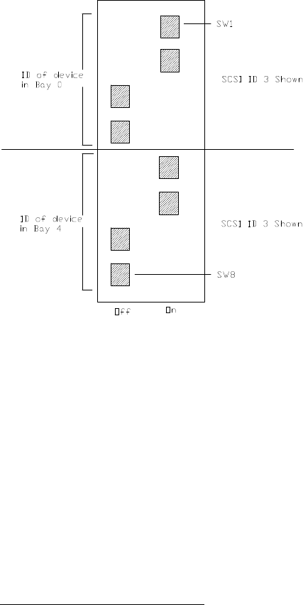
SW-1 of DPS1 corresponds to the L.S.B. of the ID of the device in bay 0, whilst SW- 4
corresponds to the MSB of the ID of the device in bay 3. SW- 5 of DPS1 corresponds to the
L.S.B. of the device in bay 4, whilst SW- 8 corresponds to the MSB of the ID of the device in
bay five.
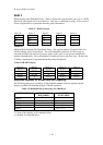
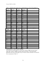
Table 2-1 shows the switch settings along with their corresponding Ids, the default
6
settings
are shown in bold text.
6
There is normally no need to change the factory default settings.
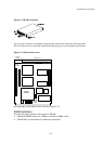
Figure 2-8 SCSI ID Switch (DPS1)