


Installation and Setup
2-9
Note Ultra SCSI has very stringent requirements regarding cable length.
Any cables connected to Ultra devices must conform to Ultra SCSI
specifications. When there are excess of 4 devices cable length should be no
greater than 1.8 metres for single ended Ultra SCSI. The implication of this
is that for any Ultra SCSI system the initiator and target will try to transfer data at
Ultra SCSI rates during the initialisation process regardless of the number of devices
and cable length. When Ultra SCSI cable length restrictions can be violated (in the case
of buses with more than 4 devices) the transfer rate must be reduced at the initiator side.
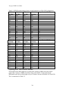
Table 2-2 Cable Lengths Vs Transfer Rates
Length in Metres Transfer Speed
6 Metres 5 MHz (10 MB/S for wide (16 bit) SCSI-2, 5MB/S for narrow SCSI-2)
3 Metres 10 MHz (20 MB/S for wide (16 bit) SCSI-2, 10MB/S for narrow SCSI-2)
3 Metres 20 MHz (4 devices or less) Ultra SCSI single ended
1.8 Metres 20 MHz (greater than 4 devices) Ultra SCSI single ended
25 Metres SCSI-2 Differential mode
Components
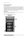
Power Supplies
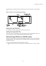
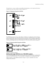
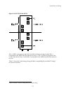
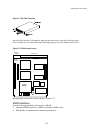
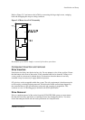
The Power Supplies are housed in removal canisters and are supplied as such. To replace a
power supply simply press the button as shown in Figure 2-9 and withdraw the carrier. The
PSU is hot pluggable
7
. Refer to the heading on page 2-14 for more details.
Note: The Power Supplies are not Auto Sensing and there are two different
types depending on the AC Input. Power Supplies for the US market are
clearly marked with a label stating 115V.
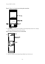
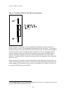
Devices
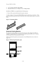
Devices are housed in two types of canisters. The top LED in the device carrier indicates SCSI
activity on the device and is green. The bottom LED is red and indicates a fault condition.
8
A
front view of the device carrier is shown in Figure 2-10.
7
To allow correct functionality of the power supply circuitry, please ensure that at least one minute has
elapsed between removal and re-insertion of the power supply unit.
Figure 2-9 Removal and insertion of a Power Supply Unit
Figure 2-10 Device carrier