


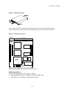


Environmental Monitoring Unit
3-5
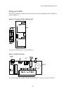
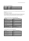
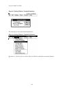
SW5 SW6 Action
Off Off No delayed power sequencing
On Off Power sequencing if only 1 PSU is available
X On Delayed power sequencing
X = Don’t Care
SW7 enables SCSI Termination power for bus one and SW8 enables SCSI Termination power
for bus two.
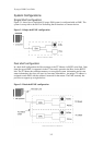
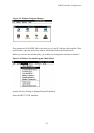
Available EMU information
More comprehensive information is provided to intelligent agents such as Eurologic’s Vision
software. Configuration, warning and status Information is available from all EMU’s. The
single EMU Storage System will provide the data shown in Table 3-4 and Table 3-5.
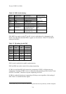
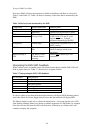
Data Name Number of Information Bytes
EMU Part No. 4 bytes
EMU Firmware Rev 2 bytes
EMU Serial No. 4 bytes
EMU Power Cycle Count 2 bytes
Status Byte 2 bytes
EMU Available 2 bytes
EMU Attention 2 bytes
Local Temp 2 bytes
EMU Data 8 bytes
Fan Insertion Count 2 bytes per Fan
PSU Insertion Count 2 bytes per PSU
SCSI Device Insertion Count 2 bytes per SCSI Devices
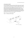
Data Name Number of Information Bytes
Master 12 bytes
Alarm Temperature 2 bytes
Critical Temperature 2 bytes
Action Byte 2 bytes
SCSI Device Status 2 bytes
Power Supply Control & Status 2 bytes
Fan Status 2 bytes
Table 3-3 Power Sequencing Signals
Table 3-4 Read Only Memory locations within the EMU
Table 3-5 Read/Write locations within the EMU