Making Measurements
27
Measuring Duty Cycle
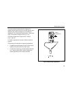
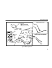
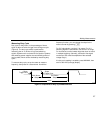
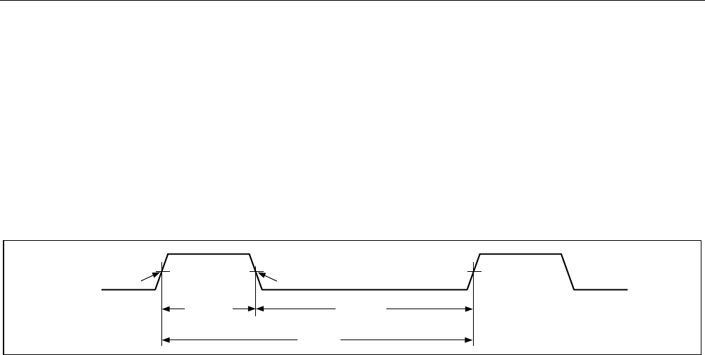
Duty cycle (or duty factor) is the percentage of time a
signal is above or below a trigger level during one cycle
(Figure 8). The duty cycle mode is optimized for
measuring the on or off time of logic and switching
signals. Systems such as electronic fuel injection systems
and switching power supplies are controlled by pulses of
varying width, which can be checked by measuring duty
cycle.
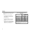
To measure duty cycle, set up the meter to measure
frequency; then press Hz a second time. As with the
frequency function, you can change the slope for the
meter’s counter by pressing T.
For 5 V logic signals, use the 4 V dc range. For 12 V
switching signals in automobiles, use the 40 V dc range.
For sine waves, use the lowest range that does not result
in multiple triggering. (Normally, a distortion-free signal
can be up to ten times the amplitude of the selected
voltage range.)
If a duty cycle reading is unstable, press MIN MAX; then
scroll to the AVG (average) display.
-Slope
Trigger Point
+Slope
Trigger Point
30% Above
+Slope
70% Below
-Slope
100%
iy3f.eps
Figure 8. Components of Duty Cycle Measurements


