80 Series III
Users Manual
42
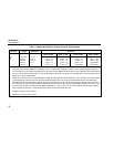
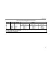
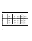
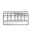
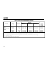
Table 11. Models 85 and 87 AC Voltage Function Specifications
Function Range Resolution Accuracy
1
50 Hz - 60 Hz 45 Hz - 1 kHz 1 kHz - 5 kHz 5 kHz - 20 kHz
2
K
3
400.0 mV
4.000 V
40.00 V
400.0 V
1000 V
0.1 mV
0.001 V
0.01 V
0.1 V
1 V
±(0.7% + 4)
±(0.7% + 2)
±(0.7% + 2)
±(0.7% + 2)
±(0.7% + 2)
±(1.0% + 4)
±(1.0% + 4)
±(1.0% + 4)
±(1.0% + 4)
±(1.0% + 4)
5
±(2.0% + 4)
±(2.0% + 4)
±(2.0% + 4)
±(2.0% + 4)
4
unspecified
±(2.0% + 20)
±(2.0% + 20)
±(2.0% + 20)
unspecified
unspecified
1. Accuracy is given as ±([% of reading] + [number of least significant digits]) at 18°C to 28°C, with relative humidity up to 90%, for a
period of one year after calibration. For Model 87 in the 4 ½-digit mode, multiply the number of least significant digits (counts) by 10.
AC conversions are ac-coupled and valid from 5% to 100% of range. Models 85 and 87 are true rms responding. AC crest factor can
be up to 3 at full scale, 6 at half scale. For non-sinusoidal wave forms add -(2% Rdg + 2% full scale) typical, for a crest factor up to 3.
2. Below 10% of range, add 6 counts.
3. Models 85 and 87 are true rms responding meters. When the input leads are shorted together in the ac functions, the meters display
a reading (typically <25 counts) that is caused by internal amplifier noise. The accuracy on Models 85 and 87 is not significantly
affected by this internal offset when measuring inputs that are within 5% to 100% of the selected range. When the rms value of the
two values (5% of range and internal offset) is calculated, the effect is minimal as shown in the following example where 20.0 = 5% of
400 mV range, and 2.5 is the internal offset: RMS = SQRT[(20.0)
2
+ (2.5)
2
] = 20.16. If you use the REL function to zero the display
when using the ac functions, a constant error that is equal to the internal offset will result.
4. Frequency range: 1 kHz to 2.5 kHz.
5. Below 10% of range, add 16 counts.


