


C141-F037-02EN 5 - 9
5.6.2 Write circuit
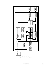
The write data is converted into the NRZ data (WDT), and is sent, together with the Write clock
(WCLK) signal, to the write circuit. The NRZ data is converted into 16/17 RLL code by the
encoder circuit, and is written to the disk.
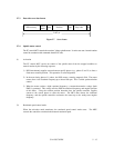
(1) 16/17 RLL encoder
This disk drive uses the 16/17 RLL recording method. The NRZ data sent from the SCSI
controller is converted into pseudorandom data by the scrambler circuit. The 16/17 RLL encoder
then converts 16-bit NRZ data into a 17-bit 16/17 RLL code.
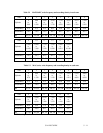
(2) Write precompensation
Write precompensation is done at write, to correct for the frequency characteristics of the
recording disk. Table 5.1 lists the algorithm for write precompensation.
Table 5.1 Algorithm for write precompensation
Bit Bit Bit Compensation
n-1 n n+1 Bit n
1 1 1 Late
1 1 0 Late
011None
010None
Late: Bit n is time shifted (delayed) from its nominal time position towards the bit
n+1 time position
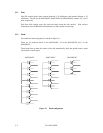
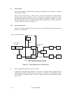
5.6.3 Read circuit
The data output from the head IC is converted to a fixed level. The acquired data is then sent to
the sample and hold circuit through the electrical filter circuit. The sample and hold circuit
samples data, then the viterbi detection circuit converts the data into a Logic signal (RD). The
VFO circuit generates a clock signal synchronized with RD. Based on this clock signal and RD
signal, the 16/17 decoding circuit converts data into NRZ data, and sends data to the buffer
memory.
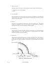
(1) AGC amplifier
The AGC amplifier automatically keeps the output amplitude level constant, even if the input
amplitude level changes. Even if the head output level changes with head characteristics and
outer or inner head position, the AGC amplifier output level is constant.