


C141-F037-02EN 5 - 13
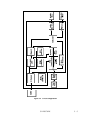
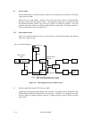
(2) Servo demodulator
As explained in 5.7.2, servo signals consist of a training segment, a Servo Mark segment, a
Position segment and a Gray Code segment, and there are 60 frames arranged around the
circumference. In the servo demodulator, the Gray Code and Position signals from the servo
signal are demodulated and used to control head positioning.
(3) SPM/VCM driver
The power amp drive signal output by the DSP (digital signal processor) is converted to a current
for driving the VCM.
This consists of a controller which controls the sensor-less spindle motor by detecting the counter
electro-motive voltage and a power MOSFET which drives the spindle motor.
5.7.2 Servo format
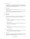
(1) Zone format
The voice coil motor is controlled to position a data head over a target cylinder, using the servo
data that has already been recorded on the servo-specific surface and the data surface.
1) Dead space
The dead space is at the innermost position of a disk. At spindle start and stop, the head is in
contact with this area of the disk.
2) Inner guard band (IGB)
IGB is located in an inner position of a disk. IGB is used to detect that actuator operation has
exceeded the ordinary seek operation range.
3) Data zone
The servo zone is the data recording part on the data side. Ordinary head seek operations are
done within this zone.
4) Outer guard band (OGB)
OGB is located in an outer position of a disk. Like IGB, OGB is also used to detect that
actuator operation has exceeded the ordinary seek operation range.
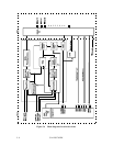
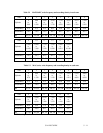
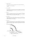
(2) Frame format
The servo pattern consists of 60 servo frames per one revolution as shown in Figure 5.6 (viewed
from track direction). One servo frame is divided into 4 areas and these areas are separated with
a gap. Figure 5.7 shows the servo frame configuration.