


8 - 10 C141-E134-01EN
bus16
bus16
bus16
bus
16
Servo
Demodulator
bus8
Control
Signal
(PWM)
Processor
Data
Head
Head
IC
Read
Channel
DSP
Drive
I/F LSI
MCU
ARM7
HDC
VCM
SPM
SPM/VCM
Combo
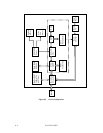
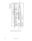
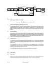
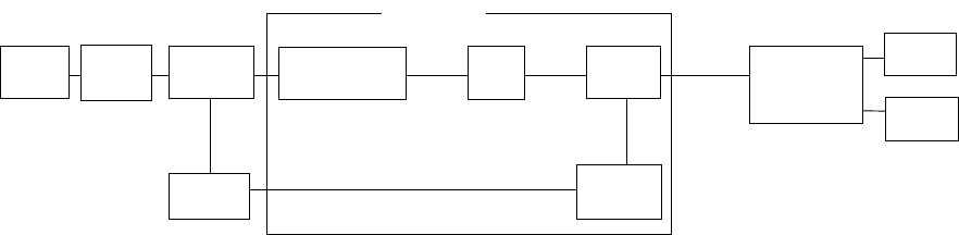
Notes: DSP controls actuator servo system.
MCU controls spindle servo system.
Figure 8.4 Block diagram of servo control circuit
(1) Processor-ASIC (Processor-application specific IC)
A DSP controls the spindle motor and the voice coil motor. The SCSI sends an instruction to the
DSP through the SCSI control MCU via drive interface. The Processor is a 1-chip ASIC, and also
contains an analog-to-digital converter, a digital-to-analog converter, RAM, and other logic
circuits.
(2) Servo demodulator
As explained in 8.7.2, servo signals consist of a training segment, a Servo Mark segment, a
Position segment and a Gray Code segment, and 84 frames for MAM series are arranged around
the circumference. In the servo demodulator, the Gray Code and Position signals from the servo
signal are demodulated and used to control head positioning.
(3) SPM/VCM driver
The SPM driver consists of a controller and a power MOSFET driver. The controller controls the
sensor-less spindle motor by checking counter electro-motive voltage, and the driver drives the
spindle motor.
The VCM driver also consists of a controller and a power MOSFET driver. The controller
converts the power amp driver signal output by the digital signal processor (DSP) into a current for
driving the VCM, and the driver drives the VCM.
The 1-chip SPM/VCM Combo driver contains power MOSFET for VCM drive.
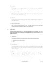
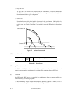
8.7.2 Servo format
(1) Zone format
The voice coil motor is controlled to position a data head over a target cylinder, using the servo
data that has already been recorded on the data surface. Figure 8.5 shows zone format.