


C141-E134-01EN5 - 6
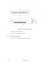
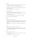
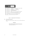
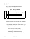
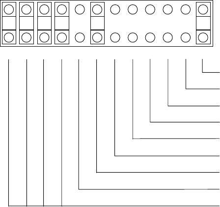
Figure 5.3 Setting terminals (CN2 on MP model only)
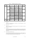
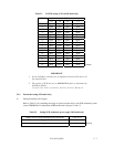
5.3.1 SCSI ID setting (MP model only)
Table 5.1 shows the SCSI ID setting. Refer to Figures 5.2 and 5.3 for terminal positioning and
allocation.
IMPORTANT
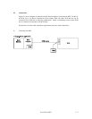
When the SCSI ID is set using the external operator panel connector
CN1, all pins listed in Table 5.1 should be open. If any of pins are
shorted, unexpected SCSI ID is set.
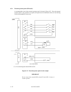
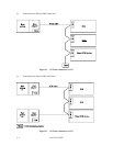
24222018161412108642
2321191715131197531
Terminator power supply: Supply
(LED signal)
(IDD Reset signal)
N.C.
Force Single Ended: LVD mode
Force Narrow: 16bit-SCSI
Motor start mode
Write protect: enabled
SCSI ID #15