


C141-E134-01EN5 - 10
5.4 Mounting Drives
5.4.1 Check before mounting
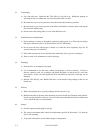
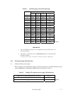
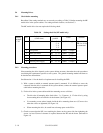
Reconfirm if the setting terminals are set correctly according to Table 5.8 before mounting the MP
model drive in the system cabinet. For setting terminals location, see Section 5.3.
The MC model drive does not require the following check.
Table 5.8 Setting check list (MP model only)
No.
Setting contents
(Check item)
Setting
position
Check Remarks
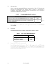
1 SCSI ID CN2 7 - 8
5 - 6
3 - 4
1 - 2
! (SCSI ID = __) Upper bus
(DB 8 to 15 PI)
not connected
2 Write protect CN2 9 - 10 ! Short ! Open
3 Motor start mode CN2 11 - 12 ! Short ! Open
4 Force Narrow CN2 13 - 14 ! Short ! Open
5 Force single ended CN2 15 - 16 ! Short ! Open
6 Terminal power supply CN2 23 - 24 ! Short ! Open
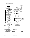
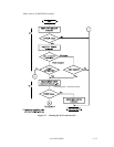
5.4.2 Mounting procedures
Since mounting the drive depends on the system cabinet structure, determine the work procedures
considering the requirements specific to each system. The general mounting method and items to
be checked are shown below.
See Subsection 4.1 for the details of requirements for installing the IDD.
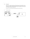
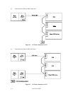
1) With a system to which an external operator panel is mounted, if it is difficult to access the
connector after the drive is mounted on the system cabinet, connect the external operator panel
cable before mounting the drive.
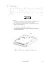
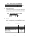
2) Fix the drive in the system cabinet with four mounting screws as follows:
• The drive has 10 mounting holes (both sides: 3 × 2, bottom: 4). Fix the drive by using
four mounting holes of both sides or the bottom. (See Figure 4.5)
• Use mounting screws whose lengths inside the drive mounting frame are 6.35 mm or less
when the screws are tightened (see Figure 4.4).
• When mounting the drive, be careful not to damage parts on the PCAs.
3) Check to ensure that the DE is not touching the frame on the system side after tightening the
screws. At least 2.5mm of clearance is required between the DE and the frame. (Indicated in
Figure 4.4)
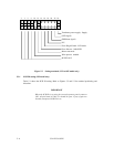
Setting
terminal
CN2