


C141-E134-01EN 4 - 11
4.3 Connection Requirements
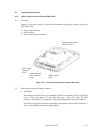
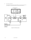
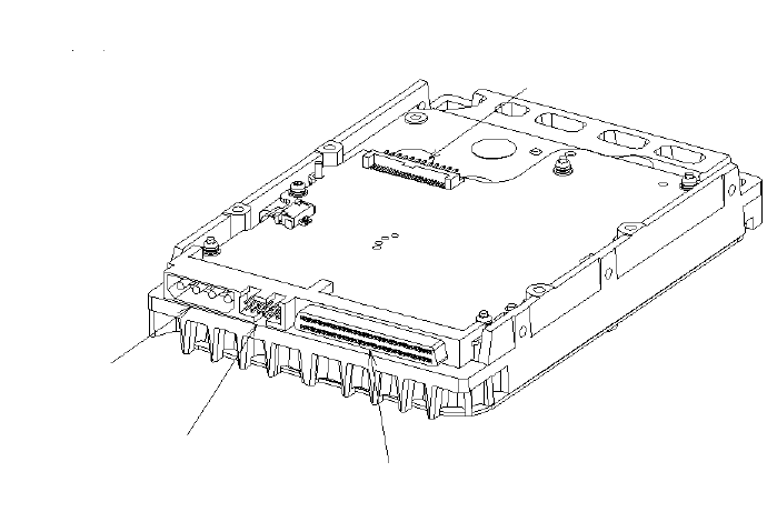
4.3.1 68 pin connector 16-bit SCSI model (MP model)
(1) Connectors
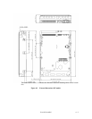
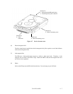
Figures 4.13 show the locations of connectors and terminals on the 68 pin connector type 16-bit
SCSI (MP) model.
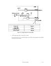
• Power supply connector
• SCSI connector
• External operator panel connector
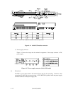
Figure 4.13 Connectors and terminals location (MP model)
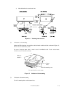
(2) SCSI connector and power supply connector
a. 16-bit SCSI
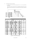
The connector for the SCSI bus is an unshielded P connector conforming to SCSI-3 type which
has two 34-pin rows spaced 1.27 mm (0.05 inch) apart. Figure 4.14 shows the SCSI
connector. See Section C.2 in Appendix C for the signal assignments on the SCSI connector.
For details on the physical/electrical requirements of the interface signals, refer to Sections 1.3
and 1.4 in the SCSI Physical Interface Specifications.
Power supply
connector
(CN1)
External operator
panel connector
(CN1)
SCSI connector
(CN1)
External operator panel
connector (CN2)