


C141-E134-01EN 3 - 9
(5) BCRC
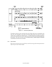
It is a 4-byte error detection code. Errors in the ID field. Single burst errors with lengths of up to
32 bits for each logical block can be detected.
(6) ECC
This is the 60-byte code that allows detection and correction of errors in the data field, which is
capable of correcting the single burst error up to 240 bits max. on the fly.
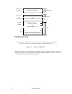
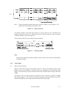
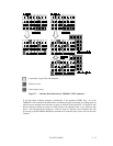
(7) PAD
A specified length of x‘00’ pattern shown in Figure 3.6 is written in this field. This field includes
the variation by rotation and circuit delay till reading/writing.
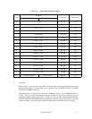
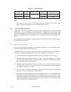
3.1.5 Format capacity
The size of the usable area for storing user data on the IDD (format capacity) varies according to
the logical data block or the size of the spare sector area. Table 3.4 lists examples of the format
capacity when the typical logical data block length and the default spare area are used. The
following is the general formula to calculate the format capacity.
[Number of sectors of each zone] = [number of sectors per track × number of tracks (heads) –
number of alternate spare sectors per cylinder] × [number of cylinders in the zone]
[Formatted capacity] = [total of sectors of all zones] – [number of sectors per track in last zone ×
number of tracks (heads) × number of alternate cylinders] ÷ [number of physical sectors in logical
block] × [logical data block length]
The following formula must be used when the number of logical data blocks are specified with the
parameter in the MODE SELECT or MODE SELECT EXTENDED command.
[Format capacity] = [logical data block length] × [number of logical data blocks]
The logical data block length, the maximum logical block address, and the number of the logical
data blocks can be read out by a READ CAPACITY, MODE SENSE, or MODE SENSE
EXTENDED command after initializing the disk medium.