


C141-E134-01EN 4 - 21
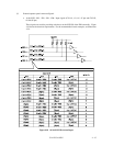
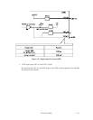
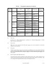
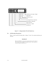
Table 4.2 Recommended components for connection
Applicable
model
Name
Par number
(Size)
Manufacturer
Reference
(Figures 4.25
and 4.30)
Cable socket (closed-
end type)
DHJ-PAC68-2AN DDK
SCSI cable
(CN1)
Signal cable
UL20528-FRX-68-
P0.635
Fujikura
S1
Cable socket housing 1-480424-0
Tyco Electronics
AMP
Contact 170148-1
Tyco Electronics
AMP
Power supply
cable (CN1)
Cable (AWG18 to 24)
S2
Cable socket housing A3B-12D-2C
HIROSE
ELECTRIC
Contact A3B-2630SCC
HIROSE
ELECTRIC
External
operator
panel (CN1)
Cable (AWG26 to 36)
S3
Cable socket housing FCN-723J016/2M
FUJITSU
TAKAMIZAWA
Contact FCN-723J-G/AM
FUJITSU
TAKAMIZAWA
MP
External
operator
panel (CN2)
Cable (AWG28)
S4
MC
SCSI
connector
(CN1)
Connector 71780-003 FCI
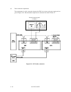
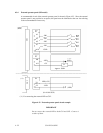
(1) SCSI cable
See Section 1.3, “Physical Requirements”, and Section 1.4, “Electrical Requirements”, in SCSI
Physical Interface Specifications.
(2) Power cable
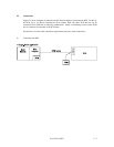
IDDs must be star-connected to the DC power supply (one to one connection) to reduce the
influence of load variations.
(3) DC ground
The DC ground cable must always be connected to the IDD because no fasten terminal dedicated
to SG is provided with the IDD. Therefore, when SG and FG are connected in the system, it is
necessary to connect SG and FG at the power supply or to connect SG of the power supply to FG
of the system.
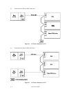
(4) External operator panel (MP model only)
The external operator panel is installed only when required for the system. When connection is not
required, leave open the following pins in the external operator panel connector of the IDD : Pins
21, 22 and pins 01 through 08 in CN2 and pins A1 through A12 in CN1.