


4
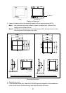
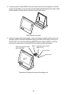
3. Loosely screw six screws (M5X15) into the holes at the rear of the display unit. Set the
screws on the display unit to the holes on the bracket and then tighten the screws. (Note
that the display unit may also be mounted in portrait orientation.)
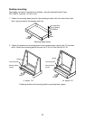
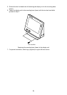
Fastening the front panel
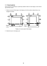
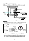
4. Fasten the power cable (local supply in case of AC power), cable from the control and
operation sections of external equipment and ground wire (local supply) at the rear of
the MU-150C. For use of the cable type 06S4078 (from a control section), cut off the
connector’s rubber cover and remove the fixing metal to enable connection.
NMEA
Cable from operation section
MJ-A10SPF0002
Cable from control section
06S4078 *5m*
Power Cable
Ground Wire
DISPLAY
UNIT
Connection of cables at the rear of the display unit