


A
P-4
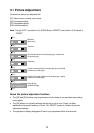
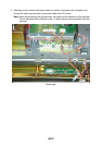
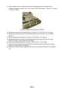
11. Fasten cables with the clamps marked with the white arrows in the figure below.
Connect the power connector to J1 on the pcb 10P3879 as follows: 1, Brown; 3, Orange;
4, Purple, 6, White.
Location of power switch and pcb 10P3879
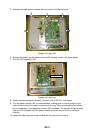
12. Fix the rear cover with 14 screws (M4 x 8). (Torque 1.47 ±0.15 Nm; 15 ±1.5 kgm)
13. Temporarily fasten the cover for the power section and connectors with 10 screws
(M3 x 8).
14. Fix four spacers for connectors. (Torque: 0.39 ±0.04 Nm; 4 ±0.4 kgm)
15. Temporarily fasten the cover for the power section and connectors with six screws
(M3 x 8). (Torque: 0.78 ±0.08 Nm; 8 ±0.8 kgm)
16. Fasten two waterproofing nuts. (Torque: 0.76 ±0.02 Nm; 7.8 ±0.2 kgm)
17. Fasten the cover near the power section and connectors with remaining four screws.
(Torque: 0.78 ±0.08 Nm; 8 ±0.8 kgm)
18. Attach the FURUNO logo (supplied) at the cavity in the upper left corner of the display
unit.