


A
P-3
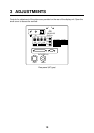
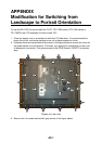
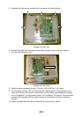
5. Unfasten the eight screws marked with the arrows in the figure below.
Display unit, rear view
6. Release the cable from the clamp marked with the gray arrow in the figure above.
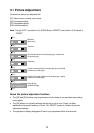
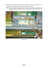
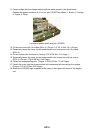
7. Turn the LCD assembly 180°.
POWER chassis
Display unit, rear view
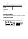
8. Fasten screws unfastened at step 5. (Torque: 0.39 ±0.04 Nm; 4 ±0.4 kgm)
9. Turn the power chassis 180° counterclockwise, making sure no load is placed on the
cable at the center of the power chassis when turning. When reassembling the display
unit to “landscape,” turn the power chassis 180° clockwise. The tape for fixing the cable
from the LCD may peel off if the power chassis is turned twice or more in the same
direction.
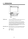
10. Fasten the cable with the clamp marked with the gray arrow in step 6.