


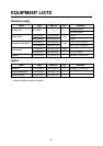

8
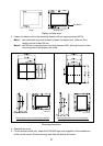
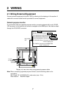
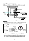
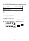
Connecting FCV-1200 series and CH-250
Using the cables designated below (or equivalent) to connect the FCV-1200 series or
CH-250 makes their interface unit of the FCV-1200 series and CH-250 unnecessary. The
mini D-SUB 15 P connector cannot be used to connect the FCV-1200 series and CH-250.
FCV-1200 Series: CONTROL UNIT
CONT
CH-250: CONTROL UNIT
REM CONT
FCV-1200 Series:
PROCESSOR UNIT CN1
CH-250: TRANSCEIVER UNIT
DATA/VIDEO OUT
24 VDC
or 100-240 VAC
Ground
Terminal
Navigator, etc.
MJ-A10SPF0002-015
06S4078
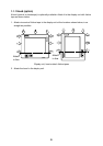
Display unit, rear view, wiring using specialty cables
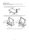
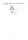
Notes on wiring
•
For AC specification, solder connector SRCN6A13-3S (supplied in installation materials)
to the power cable (DPYC-1.5 (Japan Industrial Standard) or equivalent).
Sectional view of cable DPYC-1.5
Armor
Conductor
S = 1.5 mm
2
= 1.56 mm
Armor
21
3
Connector Housing
Screw
Clamp
Tighten
set screw
Connect to
"1" and "2".
Solder Side
Armor
4-6 cm
Sheath
3mm
Armor
Soldering connector SRCN6A13-3S
1: AC (L: Live line)
2: AC(N: Neutral line)
How to solder connector SRCN6A13-3S; sectional view of cable DPYC-1.5
•
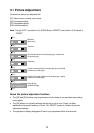
The cover of the D-sub connector of the cable 06S4078 may be removed to pass the
cable through tubing, bulkhead, etc. Use vinyl tape to bind connector wiring and rubber
cover. This allows the cable to be passed through a hole having a diameter of 30 mm.