


Magnum 6K16V Managed Fiber Switch Installation and User Guide (06/04)
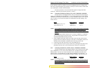
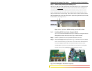
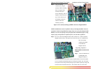
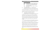
Fig 3.6.2b Granddaughter Board placed in slot A and secured with three 5/16 stand-
off’s
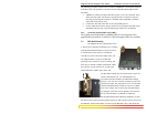
Step 3. The figure here illustrates the basic layout of an individual PM card. Each
6KPM card fits into the space provided on the main board.
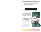
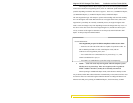
Fig. 3.6.2c Daughter Board, top view of
version for 4 copper 10/100 ports
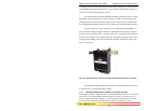
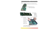
Fig 3.6.2d Daughter
Board shown
upside down
with two male
latch connectors
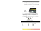
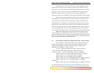
Step 4. Hold the daughter board with both hands at the end and align the two cream
color latching
connectors (male)
placed at the bottom of
the daughter board with
the other female
connector placed on the
Granddaughter and
main board. As shown
below in Fig. 3.5.2e
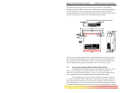
Fig. 3.6.2e Magnum 6KPM daughter board aligned with the bottom
female connector for the installation
28
www GarrettCom com
..