


Magnum 6K16V Managed Fiber Switch Installation and User Guide (06/04)
APPENDIX C: Internal DC Dual-Source Power Option
C1.0 SPECIFICATIONS - FOR MAGNUM 6K16V FIBER SWITCH
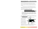
Power Supply (Internal, -48VDC Dual-Source, model # Dual-Src-48V)
DC Power Connector: First Source: “A+”, “A
-“
, 2nd Source “B
-
“, “B+”
GND: Terminal for “earth” or ground wire connection to the hub chassis
Input: Two separate sources, each at 36 - 70 VDC
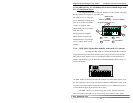
Power Supply (Internal, 24VDC Dual-Source, model # Dual-Src-24V)
DC Power Connector: First Source: “A+”, “A
-“
, 2nd Source “B
-
“, “B+”
GND: Terminal for “earth” or ground wire connection to the hub chassis
Input: Two separate sources, each at 20 - 36 VDC
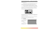
Power Supply (Internal, 125VDC Dual-Source, model # Dual-Src-125V)
DC Power Connector: First Source: “A+”, “A
-“
, 2nd Source “B
-
“, “B+”
GND: Terminal for “earth” or ground wire connection to the hub chassis
Input: Two separate sources, each at 115 - 150 VDC
With the exception of the dual DC input power connections and the power
supply, all specifications and configuration options for the Magnum 6K16V -48VDC,
24VDC and 125VDC models with this Dual-Source option are identical to those listed in
the Magnum 6K16V Fiber Switches Installation and User Guide, including Appendix B
“Internal DC Power Supply Option”
C2.0 MAGNUM 6K16V, with -48VDC, 24VDC and 125VDC Dual-Source option
The 6K16V-Switch models with the internal -48VDC, 24VDC and 125VDC
Dual-Source power supply are designed for installations where a battery plant is the
power source, and where two separate power sources are utilized in order to increase
operational uptime and to simplify maintenance.
The functionality of the Magnum 6K16V Switch -48VDC, 24VDC and
125VDC Dual-Source Option units is identical to the standard AC-powered models.
Refer to the main sections of this Installation and User Guide for a detailed description
of the Magnum 6K16V Switches.
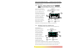
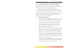
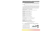
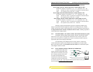
C3.0 DUAL-SOURCE OPTION, THEORY OF OPERATION
The Dual-Source DC power
option is designed using diodes inside
of the chassis on each DC power input
line. A diode is placed in each of the
four input lines (behind the four
external power connection terminals)
so that power from an external source
can only flow into the unit. This allows the unit to operate whenever DC power is
correctly applied to either or both of the two inputs
GND
FUSE
+
-
SUPPLY
A+
A-
B-
B+
GND
CHASSIS
HUB
54
www GarrettCom com
..