


Magnum 6K32T & 6K32TRC Managed Switch Installation and User Guide 05/07)
38
www GarrettCom com
..
Front panel face plate package. The Front panel faceplate package includes 3
retainer brackets and six #2-56 flat head screws.
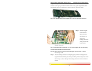
NOTE: Every 6KPM Card package comes with their matching Daughter and
Granddaughter board. The copper 6KPM card should not work properly if
mixed with other Fiber combo 6KPM card packages. Always install the PM
module separately one by one to avoid the mixing.
NOTE for Power Substations
: In support of the IEEE 1613 Class 2 standard, GCI
advises that, for substation applications, the serial RJ-45console ports are
intended for temporary connectivity to other equipment such as PCs. Since the
console port connection is temporary, it is excluded from IEEE 1613 packet-
loss testing per the 1613 standard-defined test procedure.
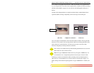
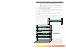
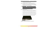
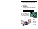
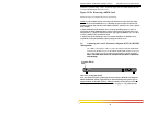
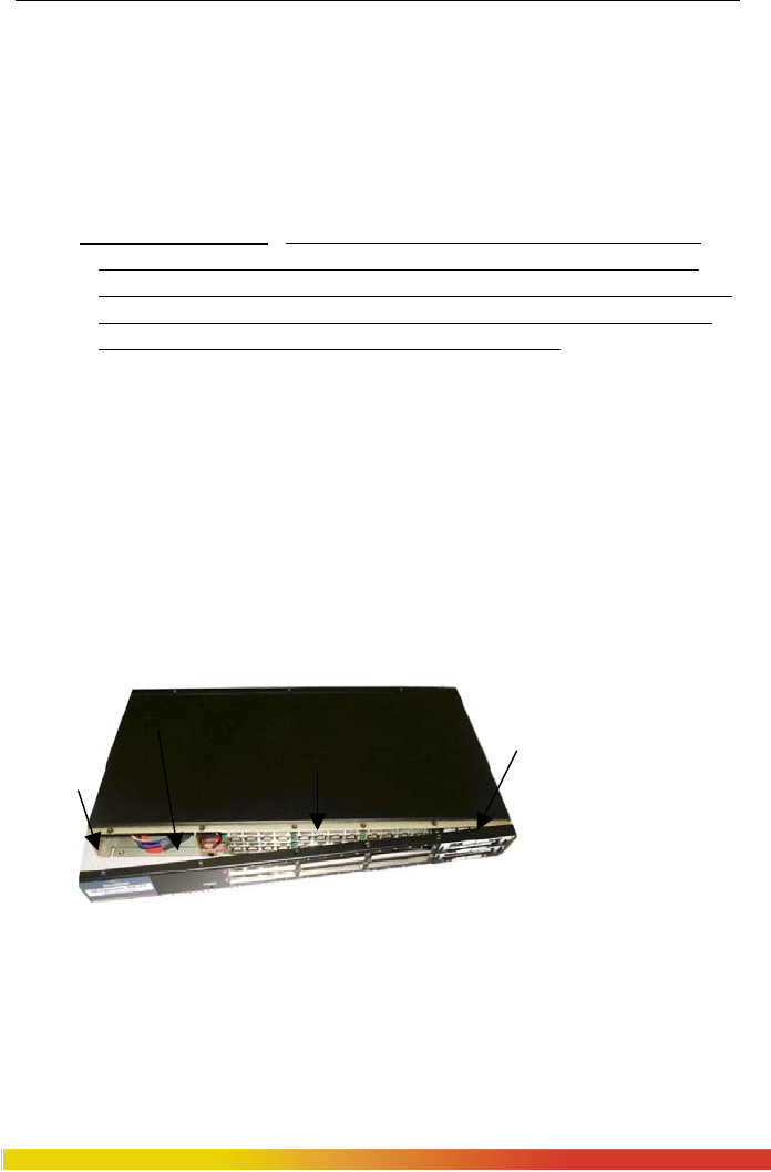
Step 2. Remove Chassis Cover
The Magnum 6K32T & 6K32TRC chassis are combined with top, bottom and
front panel parts and assembled together with the help of 17 Philips-head
screws. There are 5 screws located on the front-bottom and 3 at rear-top of the
unit and one each on the front and rear sides. First Remove the front panel
screws (total 12) as shown in the fig 3.5.1a. Once these are removed, the front
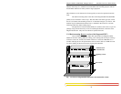
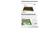
panel can be easily pulled out to the front. The top cover can be easily pulled
off to the front from the chassis base, as shown in the Fig. 3.4.1b. When the
chassis top cover has been removed, the interior of the unit is exposed.
Figure 3.5.1a: Removing front panel after the screws being removed