


Magnum 6K32T & 6K32TRC Managed Switch Installation and User Guide 05/07)
39
www GarrettCom com
..
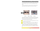
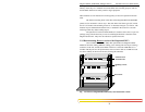
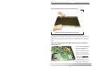
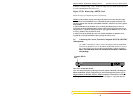
Fig 3.5.1b: Pulling out the top coved from the chassis base
Caution: Be careful not to disturb the power supply.
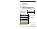
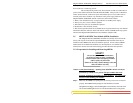
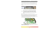
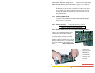
Looking down into the Magnum 6K32T & 6K32TRC unit, notice that there are
individual PM installation spaces and female latch (white) connectors provided on the far
right side of main board along with four stand-off’s for 6KPM card position. (See Figure
3.5.1c).
Figure 3.5.1c: Magnum 6K32T & 6K32TRC modular slot side (front-right side),
without chassis cover
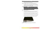
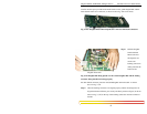
Step 3. Remove front panel
face plate retaining screws
There are one PM slot located
on the front-right side of the
chassis cover. Looking into the
vertical placed Chassis cover
of the unit, there are one
bracket with retaining screws
(#256 flat head ) which hold