


Magnum 6K32T & 6K32TRC Managed Switch Installation and User Guide 05/07)
41
www GarrettCom com
..
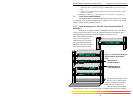
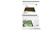
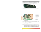
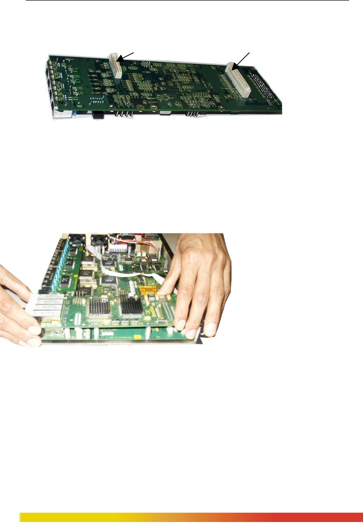
Step 3. The figure here illustrates the basic layout of an individual PM card. 6KPM
card fits into the space provided on the main board over the grand-daughter Bd. and the
male latched cream color connector( as shown in above fig. with arrow mark).
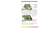
Fig 3.5.2d: Daughter Board shown upside down with two male latch connectors
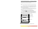
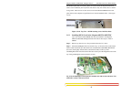
Step 4. Hold the daughter
board with both
hands at the end
and align the two
cream color
latching connectors
(male) placed at the
bottom of the
daughter board with
Fig 3.5.2e Daughter Bd. Being placed over the Grand daughter Bd. and the mating
connector being matched to lockup properly
the other female connector placed on the Granddaughter and main board. As shown
above in Fig. 3.5.2e
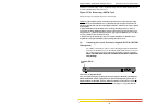
Step 5. Once the latching connectors are aligned properly and the mounting holes are
aligned with stand offs then press slowly and firmly with two fingers (as shown
below in Fig. 3.5.2f) on the top of the latching connectors until the connectors
latched