


Magnum 6K32T & 6K32TRC Managed Switch Installation and User Guide 05/07)
72
www GarrettCom com
..
C3.0 DUAL-SOURCE OPTION, THEORY OF OPERATION
The Dual-Source DC power option is designed using diodes inside of the
chassis on each DC power input line. A diode is placed in each of the four input lines
(behind the four external power connection terminals) so that power from an external
source can only flow into the unit. This allows the unit to operate whenever DC power is
correctly applied to either or both of the two inputs
C4.0 FEATURES AND BENEFITS OF THE DUAL-SOURCE DESIGN
a) The Switch unit can receive power from either input, “A” or “B”. The hub will normally draw
its power from the DC source with the highest voltage at a given time.
b) The Switch unit will not allow power to flow from a higher voltage input to a lower voltage
input, i.e. the two DC power sources are not mixed together by the hub.
c) When one correct DC input is present, the Switch will receive power if the other DC input is
absent, or even if it is connected with reverse polarity or shorted or grounded.
d) Reverse polarity connections, if they should accidentally occur on either input, will not damage
the Switch or power supply internally (nor will it blow the fuse in the internal power supply)
because of the blocking action of the diodes. This is true even if one input connection is
reversed while the Switch is operating from the other source.
e) The Switch will not receive power (and will not work) when both inputs are simultaneously
absent or are both incorrectly connected.
C5.0 INSTALLATION
This section describes the proper connection of the -48VDC, 24VDC and
125VDC dual source leads to the -48VDC, 24VDC 7 125VDC power terminal block on
the Magnum 6Ks Switch (shown in Figure )
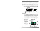
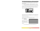
The -48VDC terminal block on the Magnum 6K32T & 6K32TRC Switch, as shown in
Fig C5.0 is located on the right rear of
the unit and is equipped with five (5)
screw-down lead posts. If it is the
reverse model it is located on the left
rear. The primary terminals are
identified as positive (A+), negative
(A-), and the secondary power
terminals as negative (B-), positive(B+). The chassis “earth” or ground (GND) is a
threaded post with a #6 nut. The Dual Source terminal block for the 24VDC and
125VDC are similar.
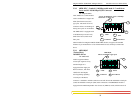
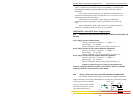
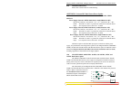
Figure C5.0: -48VDC Dual-Source, wiring connections to the External
Terminal Block on a Magnum 48VDC with Dual-Source option
Note: The GND should be hooked up first. The6K32T & 6K32TRC unit has a floating
ground, so the user may elect to Ground either + or - terminal to suit the customer’s
use.
Before connecting hot lines to the Terminal Block of –48VDC, 24VDC or
125VDC, always use a digital voltmeter to measure the output voltage of the power
supply and determine the lead which is more “+ve potential”. The more “+ve” voltage
36-70VDC
GND
A+ A- B- B+
36-70VDC