


Magnum 6K8-Series Industrial Field Switch Installation and User Guide (04/07)
absent, or even if it is connected with reverse polarity or shorted or gro
www GarrettCom com
..
unded.
ge
ernal power supply)
48V nal block on the
ig.
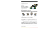
ch, as shown in Fig C5.0 is
sitive (B+). The chassis “earth” or ground (GND) is
The Dual ck for the 24VDC and
C5.0 ing connections to the
,
the power supply and
8-Series’s is similar to
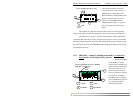
d) Reverse polarity connections, if they should accidentally occur on either input, will not dama
the Switch or power supply internally (nor will it blow the fuse in the int
because of the blocking action of the diodes. This is true even if one input connection is
reversed while the Switch is operating from the other source.
e) The Switch will not receive power (and will not work) when both inputs are simultaneously
absent or are both incorrectly connected.
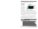
0 INSTALLATION
This section describes the proper connection of the
C5.
-48VDC, 24VDC and 125VDC dual source leads to the -
DC, 24VDC & 125VDC power termi
Magnum 6Ks Switch as shown in F
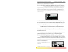
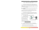
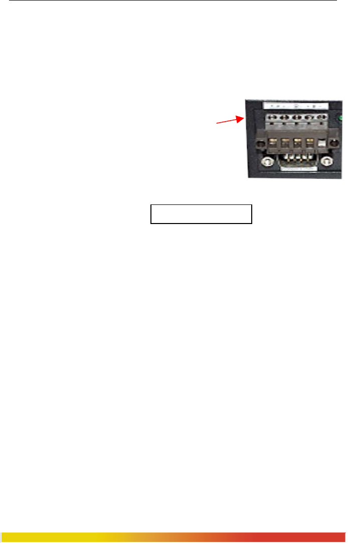
The -48VDC terminal block on the Magnum 6K8-Series Swit
located on the left front of the unit
and is equipped with five (5)
screw-down lead posts.
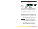
DC Terminal
The primary terminals are identified as positive (A+), negative (A-), and the secondary
power terminals as negative (B-), po
a threaded post with a #6 nut.
ure
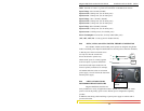
Source terminal blo
: -48VDC-Dual-Src, wir125VDC are similar. Fig
External Terminal Block on a Magnum 6K8 -48VDC
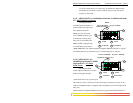
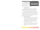
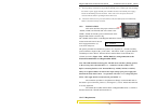
Note: The GND should be hooked up first. The 6K8-Series unit has a floating ground,
so the user may elect to Ground either + or - terminal to suit the customer’s use.
Before connecting hot lines to the Terminal Block of –48VDC, 24VDC or 125VDC
voltmeter to measure the output voltage ofalways use a digital
determine the lead, which is more “+ve potential”. The more “+ve” voltage lead from
48V or –48V supply must be connected to the post labeled “+”.
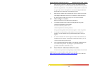
The connection procedure is straightforward. Simply connect the DC leads to
the Switch’s power terminals, positive (+) and negative (-) screws. Ensure that each lead
is securely tightened.
The 24VDC & 125VDC terminal block on Magnum 6K
that described in the –48VDC information above.
C5.1 UL Requirements
70