


Magnum 700X Mini-Concentrators Installation and User Guide (05/98)
GARRETT
22
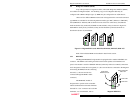
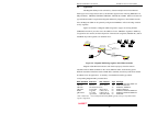
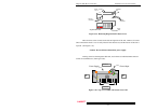
3.2.7 Connecting Twisted Pair (RJ-45, Unshielded or Shielded)
The following procedure describes how to connect a 10BASE-T twisted pair segment
to the RJ-45 port on the RPM-TP or BPM-TP. The procedure is the same for both unshielded
and shielded twisted pair segments.
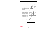
1. Using standard 10BASE-T media, insert either end of the cable with an RJ-45 plug into
the RJ-45 connector of the PM-TP. Note that, even though the PM-TP connector is shielded,
either unshielded or shielded 10BASE-T cables and wiring may be used.
2. Connect the other end of the cable to the corresponding device.
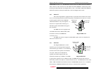
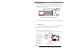
The Magnum PM-TP is equipped with a cross-over slide switch to accommodate
repeater-to-repeater connections without special cross-over connectors.
Set the slide switch to the "down" position for normal twisted pair cable segments from the PM-
TP to a user device. Set the slide switch to the "up" position for cascaded or up-link segment
connections to another repeater or hub in the network.
To help recall the right slide switch position, remember "up for up-link" !
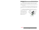
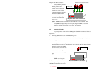
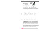
3.3 Removing the PM Face Plate
The Magnum 700X is normally received from the factory configured with all required
PM modules installed. There may be situations where additional PM cards need to be added or,
in some cases, replaced. In cases where additional PM cards are needed, the face plate for an
available slot must be removed. The following procedure describes this operation.
1. Removing Chassis Cover
STOP!!!
Be sure the power cord is unplugged
from the chassis before attempting to remove
and/or replace an PM card.
Failure to do so may result in damage to the unit
and will void the warranty.