


Magnum 700X Mini-Concentrators Installation and User Guide (05/98)
GARRETT
23
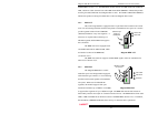
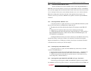
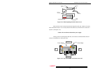
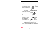
Figure 3.3a: Removing Magnum 700X Chassis Cover
There are three screws located on the left and right side of the unit. Remove all screws.
Once removed the chassis cover is easily lifted off the chassis base, and the interior of the unit is
exposed. (See Figure 3.3a).
Caution: Be careful not to disturb the power supply.
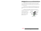
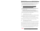
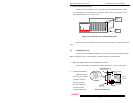
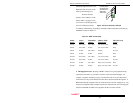
Looking down into the Magnum 700X unit, notice there are individual PM connector
sockets for each PM card. (See Figure 3.3b).
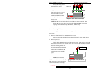
Figure 3.3b: Top View of 700X with Chassis Cover Off
Ventilation
Slots
Chassis
Cover
Magnum 700X
Magnum 700X Chassis
Chassis
Base
Recessed
Screw Holes
Recessed
Screw Holes
Power Supply
Power
Input
Back of Unit
Front of Unit
Right
Side
Left
Side
PM Sockets