


Magnum 700X Mini-Concentrators Installation and User Guide (05/98)
GARRETT
24
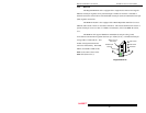
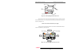
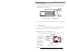
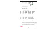
2. Remove PM Retaining Screws
On the front of the unit there are two retaining screws for each PM card slot. These
screws are used to secure the face plate in position. These screws are also used to secure
individual PM modules. (See Figure 3.3c).
Figure 3.3c: Front Panel View - PM Retaining Screws
Once the face plate or PM has been removed, proceed to Section 3.4 and install the PM
card.
3.4 Installing PM Cards
Up to seven assorted PM (Port Module) cards are easily installed in the Magnum 700X
Mini-Concentrator chassis. The installation procedure for PMs is described below.
1. Removing 700X Chassis Cover and PM Retaining Screws
Follow the procedure described for Face Plates in Section 3.3, Steps 1 and 2, above.
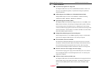
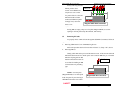
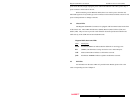
2. Installing the PM Card
Each PM card fits
easily into any available
connector socket slot.
Align the connector
pins on the PM card
with the connector
socket inside the unit.
Side View of PM Card
Magnum 700X Chassis
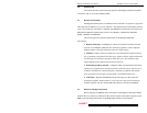
Magnum 700X
Chassis
Base
PM
Retaining
Screws
RPM Retaining
Screw Hole
Eight (8) Pin
PM Conector
PM Mounting
Plate
- PM Media Interface
- ST (Fiber)
- SMA (Fiber)
- BNC (ThinNet)
- AUI (ThickNet)
- RJ-45 (Twisted Pair)
- DTE (RS-232)
- SMF (Fiber)
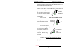
PM
Retaining
Screw Hole
Magnum
PM Card