www.gateway.com
29
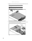
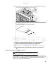
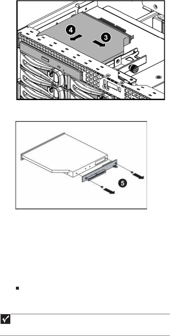
6 Move the optical drive to the right (3), then push the optical drive (4) out of the bay.
7 Unscrew the two screws (5) that secure the optical drive interface board to the optical drive,
then remove the interface board.
8 Using the two screws you just removed, attach the optical drive interface board to the
back of the new optical drive.
9 Insert the optical drive into the optical drive bay, aligning it with the clips on the right and
left sides.
10 Secure the assembly by tightening the thumbscrew you previously loosened.
11 Attach the 44-pin optical drive cable to the back of the interface board.
12 Follow the instructions in “Closing the server case” on page 27.
13 Reinstall the bezel, if required, by snapping it into place on the front of the chassis.
14 Reconnect all power cords and peripheral device cables, then turn on the server.
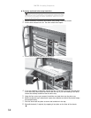
Removing and installing a hard drive
Use this procedure to add or replace a hard drive in a hot-swap bay. Your server supports as
many as twelve 1-inch high, 3.5-inch hot-swap SATA and SATA II hard drives or twelve 1-inch
high, 3.5-inch hot-swap SAS hard drives. You can purchase additional drives through your
Gateway Sales or Customer Care representative.
Important
Gateway tests and verifies the operation and compatibility of the drives it sells.
Especially in a hot-swap or mission-critical environment, additional or replacement drives
must conform to Gateway standards.


