


32
I
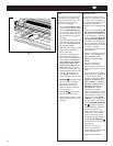
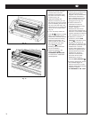
FILM ALIGNMENT PROCEDURE
The film supply shafts of the
ULTIMA 65-1 Laminator come with
pre alignment holes on the right
side for 9 in. (21 cm), 12 in. (31
cm), 18 in. (46 cm), and 25 in. (64
cm) film widths. Loosen the locking
screw on the right side retaining
collar and move to the
corresponding hole to match the
width of your roll of film. Tighten
the locking screw in the pre drilled
hole.
FILM TENSION ADJUSTMENT
Proper film tension, known as
brake tension, is the minimum
amount required to eliminate
wrinkles in the finished item. The
film tension is set at the factory.
Periodic adjustments should not be
necessary unless other than 1.0 or
1.5 mil GBC film is used or the
lamination is curling up or down.
Film tension may be checked
occasionally to assure that the
adjustment is not required.
The film should be taut. A properly
adjusted roll of film should not
require excessive force to turn by
hand. Film tension should be
enough to introduce a minor amount
of drag as the film unrolls.
Insufficient tension causes
wrinkles, while too much tension
causes stretching (necking).
Uneven tension between the top
and bottom rolls create curl. Too
much upper tension creates
upward curl while too much bottom
tension causes downward curl.
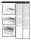
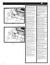
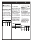
1. To adjust the bottom brake. Push
and the hold the brake lever
located on the left side frame by
the roll of film (Fig. 20).
2. Rotate the roll of film until the
lever engages the internal
mechanism.
3. Refer to Fig. 21 for the proper
rotation of the film to increase
the tension.
4. Release the brake lever and
check the tension by rotating the
roll of film. Resistance should be
slight, not forced.
5. To adjust the top brake, repeat
steps 1 through 4.
6. Laminate some test samples to
check for proper tension.
Further adjust if necessary.
Fig. 20
Fig. 21
Brake lever
Increase
Decrease
ALLINEAMENTO DEL FILM
Gli alberi della plastificatrice ULTIMA
65-1 vengono forniti completi di fori
sul lato destro per film con
larghezza di 21 cm, 31 cm, 46 cm e
64 cm. Allentare la vite di montaggio
posta sulla ghiera di destra e
spostarla in corrispondenza del
foro adatto rispetto alla larghezza
della bobina del film. Stringere la
vite di bloccaggio nel foro
predisposto.
REGOLAZIONE DELLA TENSIONE
DEL FILM
Un’adeguata tensione del film, detta
tensione frenante, è rappresentata
dal valore di tensione minimo
richiesto per prevenire
corrugamenti sull’articolo finito. La
tensione del film è impostata in
fabbrica. Non è necessario
effettuare regolazione se si usa un
film GBC da 1 o 1,5 mil, a meno che
la plastificazione presenti
accartocciamenti verso l’alto o
verso il basso. La tensione del film
può essere controllata
occasionalmente per verificare che
la regolazione sia corretta.
Il film deve essere ben teso. Una
bobina di film ben regolata non
dovrebbe richiedere forza
eccessiva per essere girata a
mano. La tensione del film
dovrebbe essere sufficiente per
introdurre un minimo attrito frenante
mentre il film si svolge. Tensione
insufficiente può causare
corrugamenti, mentre eccessiva
tensione può causare stiramenti.
Tensione non uniforme tra le bobine
inferiore e superiore è causa di
accartocciamenti. Eccessiva
tensione superiore causa
accartocciamenti verso l’alto,
mentre eccessiva tensione
inferiore causa accartocciamenti
verso il basso.
1. Per regolare il freno inferiore:
Premere e mantenere premuta la
leva del freno sul lato sinistro
rispetto al rullo di film (fig. 20).
2. Girare il rullo di film fino a
quando la leva raggiunge il
meccanismo interno.
3. Per capire quale sia la rotazione
corretta affinché il film aumenti la
tensione, consultare la figura 21.
4. Rilasciare la leva del freno e
controllare la tensione facendo
girare il rullo di film. La
resistenza deve essere leggera
e non forzata.
5. Per regolare il freno superiore,
ripetere le fasi da 1 a 4.
6. Plastificare alcuni campioni di
prova per verificare la
correttezza della tensione e, se
necessario, effettuare ulteriori
regolazioni.