


g
GE
OPM_SGS_ISG_M22_M30_0US_V011.doc 19/38 Installation Guide
SG Series
225 & 300 kVA
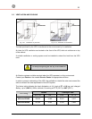
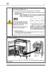
3.7.3 Battery over current protection and wire sizing
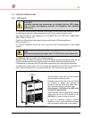
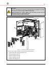
• Please read the safety precautions at the front of this guide carefully, and thoroughly
review the Battery manufacturers installation and maintenance manual before connecting
the batteries to the UPS.
• If the UPS system has been purchased with an accompanying Battery Cabinet, that
cabinet should have an integral
Battery Circuit Breaker
.
If the UPS has been purchased without a Battery Cabinet or remote rack mounted
batteries are to be used then DC over current protection must be provided by others.
• Choose an appropriate DC fuse or circuit breaker using the current data in the chart
below.
• Minimum Battery Cable requirement is based on the current data below.
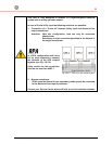
The AC values below are current ratings per phase.
These maximum and nominal ratings should be considered when choosing the
appropriate AC over current protection device.
NEC (National Electric Code) Section 210-20 a rules must be applied.
DC current rating is the maximum battery discharge current which the UPS allows.
(See Fig. 3.7.1-1 and 3.7.1.2)
AC Input
Rectifier
AC Input
Bypass
AC Input DC Input
F1 F3
Nom. Max.
F2
Nom. Max.
F4
SG Series 225 kVA
301 A 360 A 271 A 301 A 360 A 401 A
SG Series 300 kVA
401 A 480 A 361 A 401 A 480 A 535 A
Size of Branch Circuit Over current Protection - All Models: - "CAUTION - To reduce
the risk of fire, only connect UPS to a circuit provided with (See below) maximum
amperes branch circuit over current protection in accordance
with the NEC (National Electric Code), NSI / NFPA 70
AC Input
Rectifier
AC Input
Bypass
AC Input DC Input
F1 F2 F3 F4
SG Series 225 kVA
450 A
350 A 450 A 600 A
SG Series 300 kVA 600 A 500 A 600 A 700 A
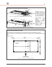
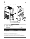
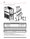
WIRING
Wire sizing according to
NEC Section 210-20 (a) Table 310-16
Use 75°C (167°C) copper wire
Wiring requirements:
AC INPUT RECTIFIER:
3-Phase, 3 wire plus Ground
AC INPUT BYPASS: 3-Phase, 4 wire plus Ground
AC OUTPUT:
3-Phase, 4 wire plus Ground
DC INPUT: 2 wire (positive and negative) plus Ground
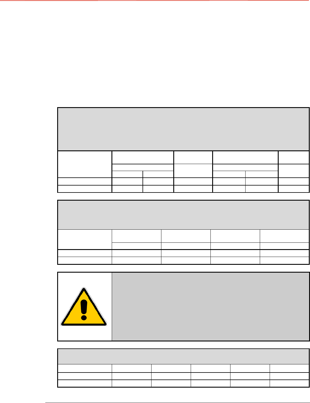
Maximum cable diameter that compression lugs can accept.
Refer to torque specifications table for torque requirements.
Rectifier Input Bypass Input DC Input AC Output GND
SG Series 225 kVA
2 x 500 kcmil 2 x 500 kcmil 2 x 750 kcmil 2 x 500 kcmil 350 kcmil
SG Series 300 kVA
2 x 750 kcmil 2 x 500 kcmil 2 x 750 kcmil 2 x 500 kcmil 350 kcmil