


g
GE
OPM_SGS_ISG_M22_M30_0US_V011.doc 29/38 Installation Guide
SG Series
225 & 300 kVA
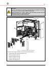
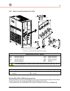
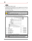
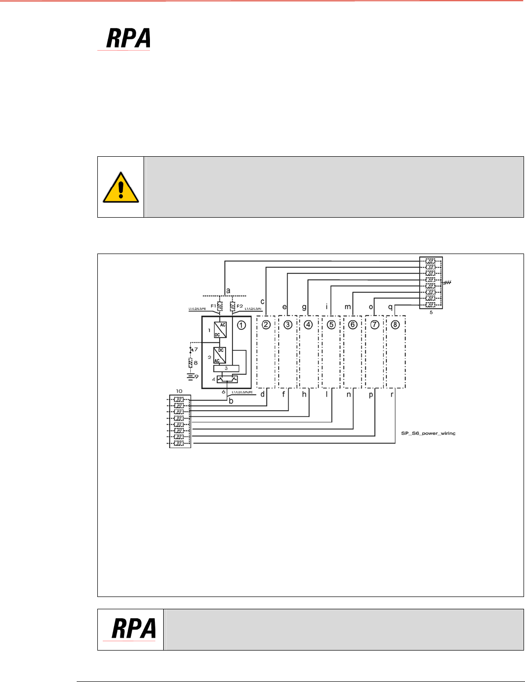
3.9 POWER WIRING OF PARALLEL UNITS
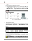
To guarantee good Load sharing between the units of a parallel system, we recommend it is
recommended that the cable length from the input distribution board (5) to the output
distribution board (10) are the same length for each unit (a+b = c+d = e+f = g+h = i+l = m+n =
o+p = q+r). Tolerance: +/-10%.
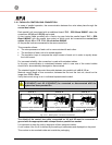
The AC input power of the Bypass must be the same for all units of the parallel system - no
phase shift allowed between units.
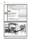
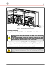
It is strongly recommended that no transformers, automatic circuit breakers
or fuses should be inserted between the unit’s output and the Load common
bus bars.
However, it is recommended that a disconnect or isolation switch be inserted
in order to totally isolate a unit if needed
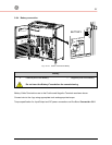
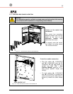
Verify that power wiring and control wiring are run in separate conduits or cable trays.
UPS input cables must be run in separate conduits from the output cables.
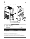
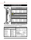
Fig. 3.9-1 RPA Parallel System
1
= Rectifier
c
= Unit Number 1
2 = Inverter
2
= Unit Number 2
3
= Electronic Bypass
3
= Unit Number 3
4 = Manual Bypass
4
= Unit Number 4
5
= Input Utility Distribution
5
= Unit Number 5
6 = Unit Output Load
6
= Unit Number 6
7 = External Battery MCB
7
= Unit Number 7
8 = External Battery fuse
8
= Unit Number 8
9 = External Battery
10 = Common Busbar and Output Load Distribution
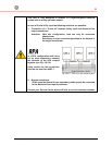
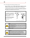
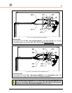
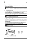
In a RPA configuration with 3-wire kit, it’s most important to connect the
Neutrals of the UPS outputs together (see Fig .3.8.2-2 and 3.8.3-2).
Cable section for this connection shall be not less then AWG 1