


g
GE
OPM_SGS_ISG_M22_M30_0US_V011.doc 31/38 Installation Guide
SG Series
225 & 300 kVA
SGT5000_100-150_RPA-IM0048_02
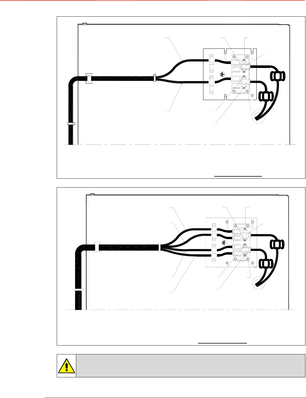
JP3
JP1
JP4
IM 0048
JP2
JP1 JP2
JP4
JP3
JB1
JA1
JB
JA
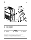
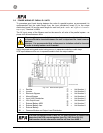
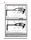
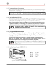
Fig. 3.10-2 Bus connection on terminal units
Terminal units
On the parallel bus PCB “P34 – Bus Interface IM0048”, of the first and last units (terminal)
of the parallel system the Jumpers JP1, JP2, JP3 and JP4 must be inserted
.
JB1
JA1
JP2JP1
JP3
JP4
JP3
JP2
JP1
JP4
IM 0048
JB2
JA2
SGT5000_100-150_RPA-IM0048_03
JA
JB
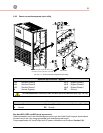
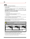
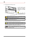
Fig. 3.10-3 Bus connection on intermediate units
Intermediate units
On the parallel bus PCB “
P34 – Bus Interface IM0048
”
of the
intermediate units
of the
parallel system the Jumpers JP1, JP2, JP3 and JP4 must be removed
.
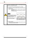
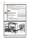
In a parallel system composed of 2 or more units, only the first and last units
(having 1 input JA and JB free) have the Jumper JP1, JP2, JP3 and JP4 inserted on
parallel bus PCB “P34 – Bus Interface IM0048” (see Fig. 3.10-2).