


g
GE
OPM_SGS_ISG_M22_M30_0US_V011.doc 21/38 Installation Guide
SG Series
225 & 300 kVA
3.8 WIRING CONNECTION
WARNING!
UPS installation and connection must be performed by qualified service
personnel only.
3.8.1 Power connections
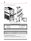
Input/output and DC connections are provided with compression lugs.
Please refer to chart for torque specifications.
Carefully read the following recommendations before proceeding:
• Ensure that the AC and DC external isolators are OFF and locked to prevent their
inadvertent operation.
• Do not close any external isolators prior the commissioning of the equipment.
•
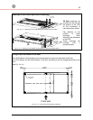
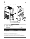
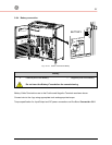
The preferred power cable entry location for installation purposes is from the right side of
the UPS, either top or bottom.
To facilitate the terminations remove the right side panel in order to access the input/output
terminal lugs.
In case of cable entry from the top of the cabinet, remove the cover plate fitted on the roof
and provide for a suitable isolated protection cover.
In case of cable entry from the bottom remove cover plate and perform the same
procedure.
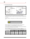
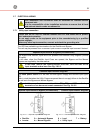
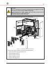
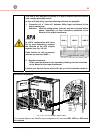
• If the UPS is installed in such a way that the accessibility to the right side panel is reduced,
field wiring connections can be made from the front side by removing the front right side
panel protection cover/panel ( D ) as indicated in Fig. 3.8.1-1 be advised that installation
performed from the front position will give the installer reduced visibility to the terminal lugs.
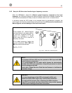
• The input/output cables must be connected in clockwise phase rotation for both
Bypass and Rectifier Input Terminals if separate, taking care to avoid risk of short
circuit between different poles.
•
The grounding and neutral connection of the electrical system must be in accordance with
local regulations.
• In case of additional cabinets containing batteries, input/ output transformers, etc, their
ground terminals must be connected to the UPS main ground terminal.
• Once the power cables have been connected, re-install the internal safety shields and close
the cabinets by re-installing all external panels.
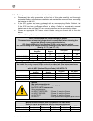
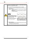
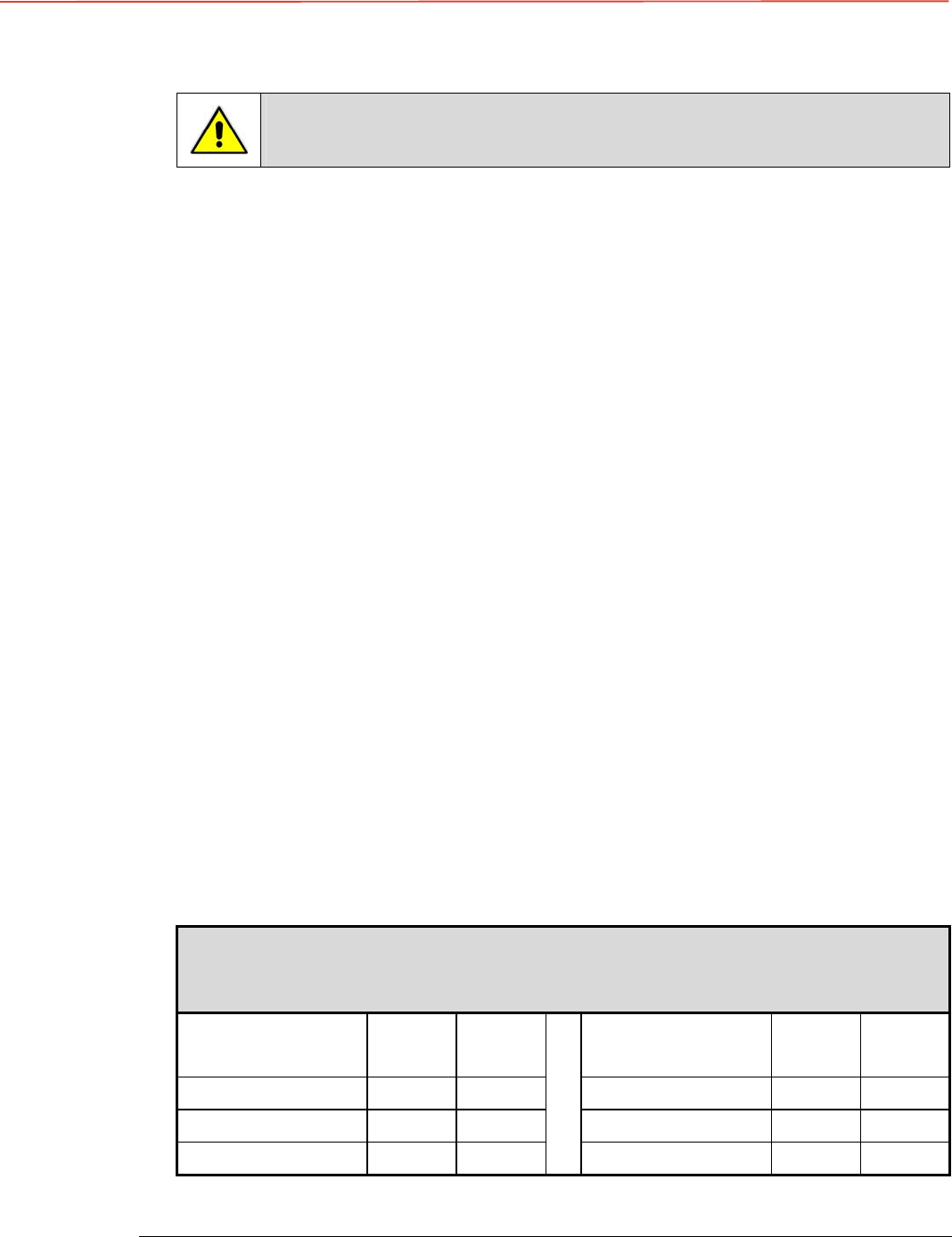
Torque Specifications
Mechanical Compression Lugs
Input / Output / Battery and GND
WIRE SIZE RANGE
AWG / kcmil
Lb - in
Nm
WIRE SIZE RANGE
AWG / kcmil
Lb - in
Nm
6 – 4
110 12.4
3/0 – 200
250 28.2
3 – 1
150 19.6
250 – 350
325 36.7
1/0 – 2/0
180 20.3
500 – 750
375 42.4