


g
GE
OPM_SGS_ISG_M22_M30_0US_V011.doc 33/38 Installation Guide
SG Series
225 & 300 kVA
SGS_225-300_RPA control bus cable_02US
Q1
Q2
2
4
3
1
3
4
2
1
JA1
1
3
4
2
4
2
3
1
Q1
Q2
JB1
U
P
S
1
U
P
S
2
JA2
JB2
un
i
t
3,
4
,
5
,
N
e
x
t
p
a
r
a
l
l
e
l
6,
7,
8
JB1
JA1
JA
JB
JA
JA2
JA1
JB1
JB2
JB
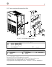
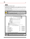
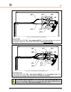
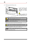
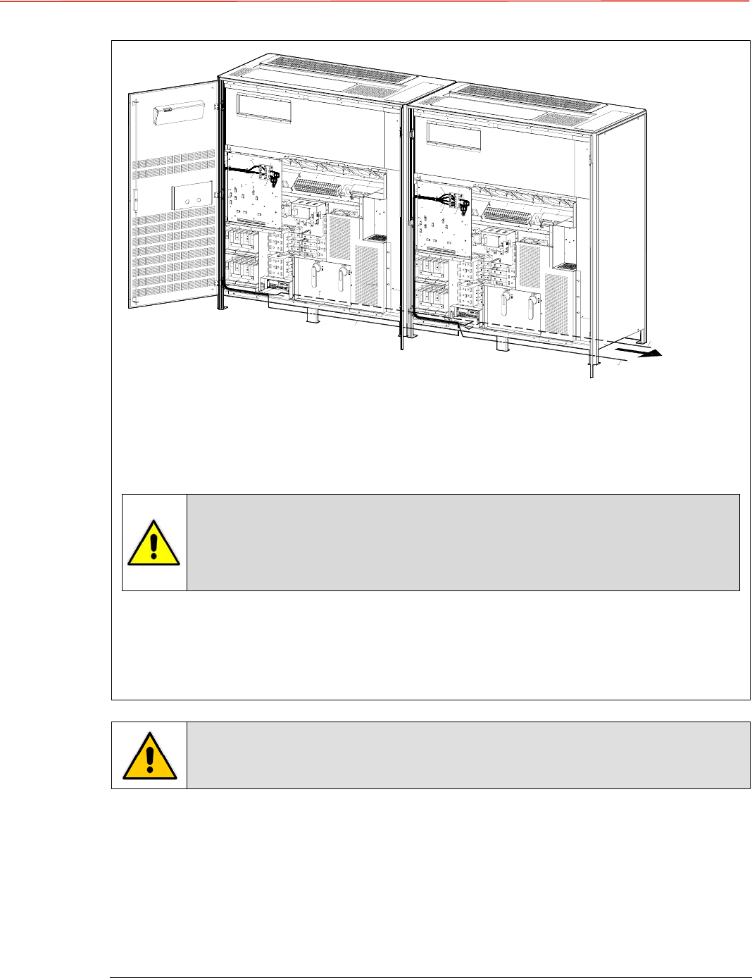
Fig. 3.11-3 Control Bus cable routing and connection
Control bus cables routing
Place and fix the cables
JA-1/2/3/4/5/6/7
and
JB-1/2/3/4/5/6/7
inside the UPS cabinets in the
position illustrated in the drawing.
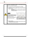
Pay attention when cabling and routing the bus cables JA and JB inside the
UPS cabinet.
In case one unit should be removed from the parallel system, the bus cables
JA and JB must be removed from the cabinet without disconnecting them
from the metal plate where the sockets JA and JB are located.
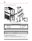
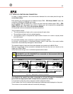
For reliability reasons the cables
JA-1/2/3/4/5/6/7
and
JB-1/2/3/4/5/6/7
connecting the units
should be run in separated protected conduits (as indicated in fig. 3.11-3) separated from the
power cables.
It is important that the cable JA must be the same length as cable JB.
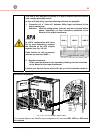
The connection of the control bus cable in a UPS system already powered
requires a special reset operation, which can be made by only a trained
operator.